Folding knife with blade replacement mechanism

Inactive Publication Date: 2008-03-06
KANTAS PROD
View PDF23 Cites 12 Cited by
  • Summary
  • Abstract
  • Description
  • Claims
  • Application Information

AI Technical Summary

Benefits of technology

[0006]It is an object of the present invention to provide a folding knife comprising a blade having a fastening hole, a tang, and a handle. The tang comprises a front cavity. A rear end of the tang distal the cavity is pivotably secured to a front end of the handle. Thus, both the tang and the blade can pivotably either receive in a lengthwise slot of the handle when not in use or extend out of the slot for use. The tang comprises an integral flexible tongue. One end of the tongue is formed with the tang and the other end thereof is disposed corresponding to the cavity. The tongue further comprises a projection on its inner surface facing the cavity. A push member is provided on a top edge of the tang facing the tongue. For mounting the blade, a user may slide the push member rearward to push an open end of the tongue away from the cavity, insert the blade into the cavity until the fastening hole lines up with the projection, and slide the push member forward to bounce the projection back into the fastening hole for fastening the blade in the cavity. To the contrary, a user may slide the push member rearward to push the open end of the tongue away from the cavity to disengage the projection with the fastening hole prior to detaching the blade from the cavity for replacement. By configuring the tongue as an integral part of the tang, materials and manufacturing cost are greatly reduced, assembly steps are significantly decreased, and the tongue is fully protected.

Problems solved by technology

However, the prior art folding knife suffered from several disadvantages.
These assembly steps are very complicated.
Further, it may consume excessive time and involve intensive labor.
This really bothers manufacturers of the art.
Moreover, an excessive number of components and a variety of components inevitably increase the manufacturing cost.
This in turn has the drawback of increasing difficulties of pivoting the tang 100 into the slot 301.
All of these bring trouble and inconvenience to a user.

Method used


Image

  • Folding knife with blade replacement mechanism
  • Folding knife with blade replacement mechanism
  • Folding knife with blade replacement mechanism

Examples


Embodiment Construction

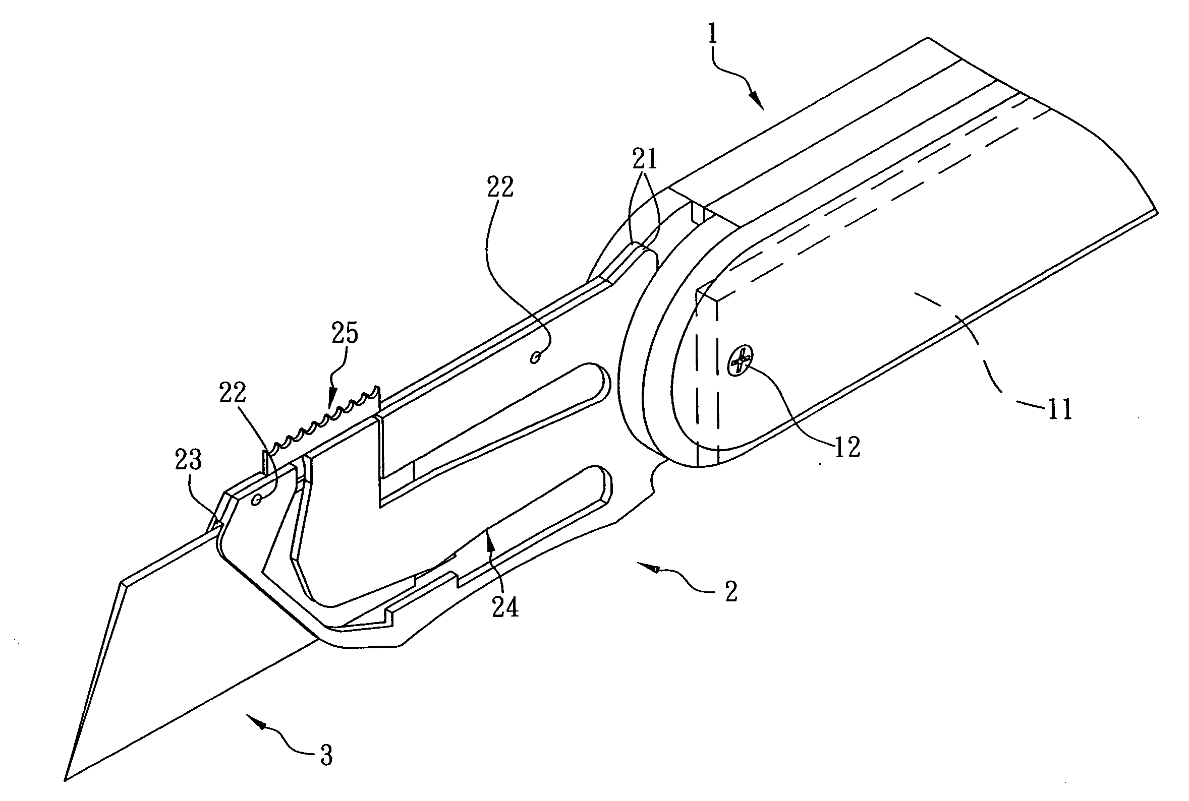
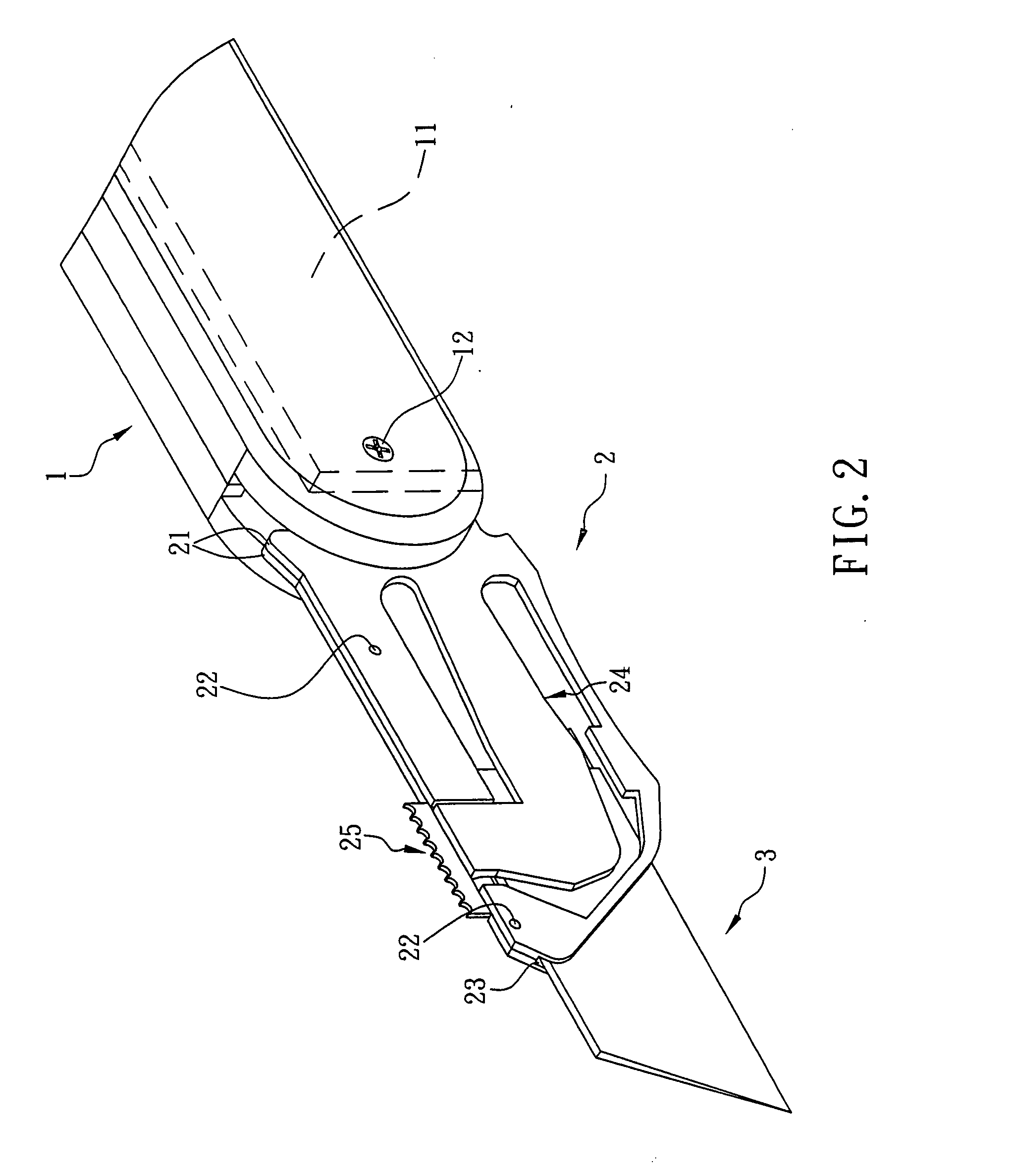
[0014]Referring to FIG. 2, a folding knife in accordance with a first preferred embodiment of the invention comprises a blade 3, a tang 2, and a handle 1. Each component is discussed in detailed below.

[0015]The tang 2 comprises two elongate pieces 21 of substantially rectangular in shape, a plurality of fasteners 22 for fastening the pieces 21 together, and a front parallelogram cavity 23 provided in one piece 21 for anchoring a rear end of the blade 3 as detailed later. Rear portions of the pieces 21 are pivotably secured to a front end of the handle 1 by means of a pin 12. Thus, both the tang 2 and the blade 3 can pivotably either receive in a lengthwise, central slot 11 of the handle 1 when not in use or extend out of the slot 11 for use.

[0016]Referring to FIG. 3 in conjunction with FIG. 2, the cavity 23 is defined between and by the pieces 21 when the pieces 21 are fastened together. An L-shaped flexible tongue 24 is extended from a rear end of the other piece 21. The tongue 24 ...


PUM


Abstract

The present invention is to provide a folding knife comprising a handle, a blade having a fastening hole and a tang having a front cavity and a rear end distal the cavity pivotably secured to a front end of the handle. The tang comprises an integral flexible tongue with one end formed with the tang and the other end disposed corresponding to the cavity, a projection on the inner surface of the tang facing the cavity and a push member provided on a top edge of the tang facing the tongue. For mounting the blade, a user may slide the push member rearward to push an open end of the tongue away from the cavity, insert the blade into the cavity until the fastening hole lines up with the projection, and slide the push member forward to bounce the projection back into the fastening hole for fastening the blade in the cavity.

Description

FIELD OF THE INVENTION[0001]The present invention relates to folding knifes and more particularly to such a folding knife having a mechanism for enabling a user to easily replace a used blade (e.g., one becomes dull) with a new one.BACKGROUND OF THE INVENTION[0002]There is a rapid, significant progress of technologies in recent several decades. Products related to these technologies include high-technology products as well as consumer goods which are closely tied to our daily life. For having better standards of living, it is desirable among people to improve many kinds of consumer goods by eliminating drawbacks associated therewith.[0003]Knifes are a typical kind of tool frequently used in our daily life. Also, there are many types of knifes available. For example, a conventional folding knife is shown in FIG. 1. The folding knife comprises a tang 100, a blade 200, and a handle 300. The hollow, rectangular tang 100 comprises a circular through hole 151 on one side surface, and a re...

Claims


Application Information

Patent Timeline
IPC IPC(8): B26B1/02
CPCB26B5/00
Inventor CHENG, YANG-FU
Owner KANTAS PROD
Why Eureka
Try Eureka