Internal Glass Holder

Inactive Publication Date: 2008-03-06
VIDA INT AB
View PDF7 Cites 13 Cited by
  • Summary
  • Abstract
  • Description
  • Claims
  • Application Information

AI Technical Summary

Benefits of technology

[0004]One object of the present invention therefore is to eliminate the period of rest after the application of the inner c

Problems solved by technology

Many kinds of glue layers that are also sealing in some cases need a co

Method used


Image

  • Internal Glass Holder
  • Internal Glass Holder
  • Internal Glass Holder

Examples


Example

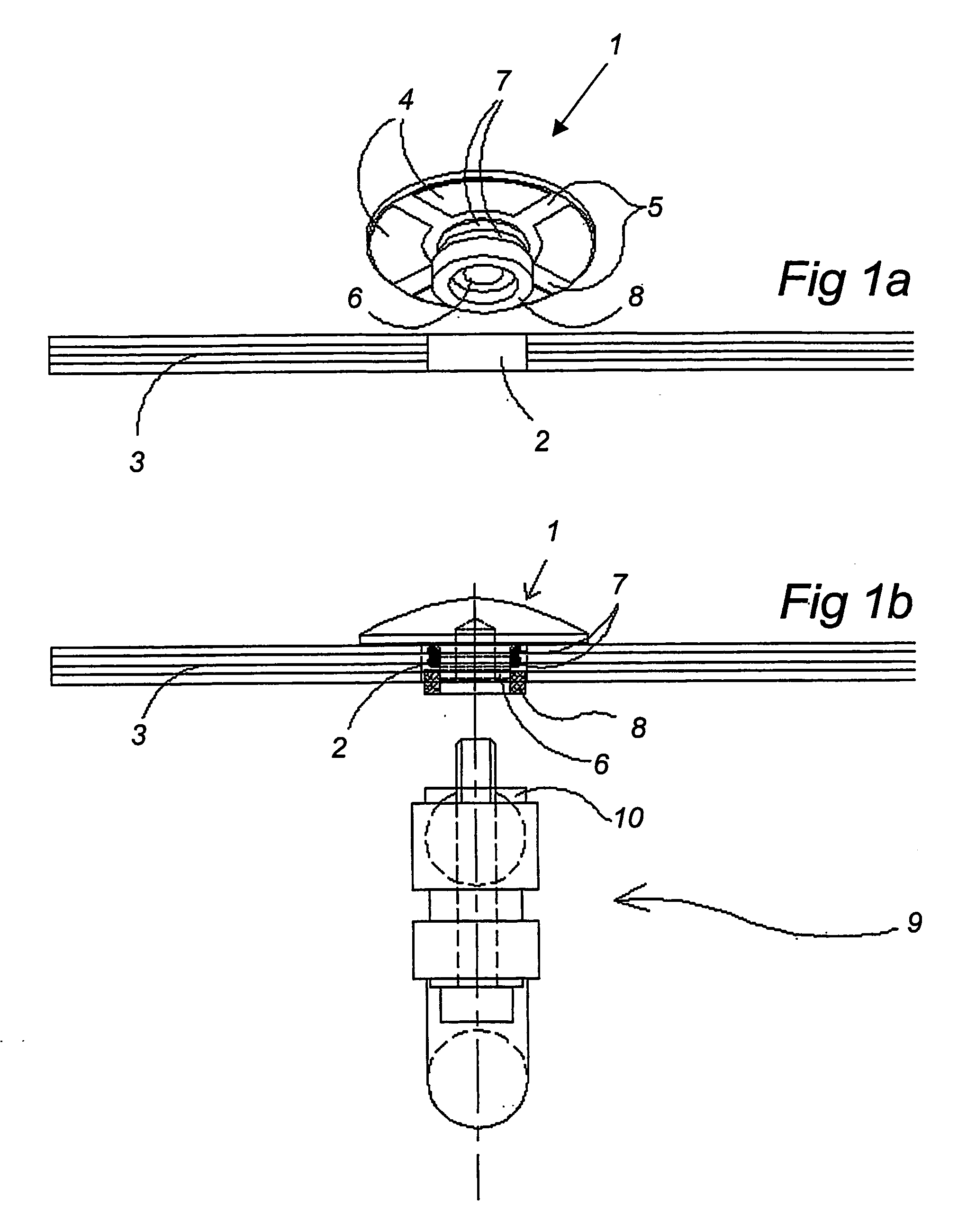
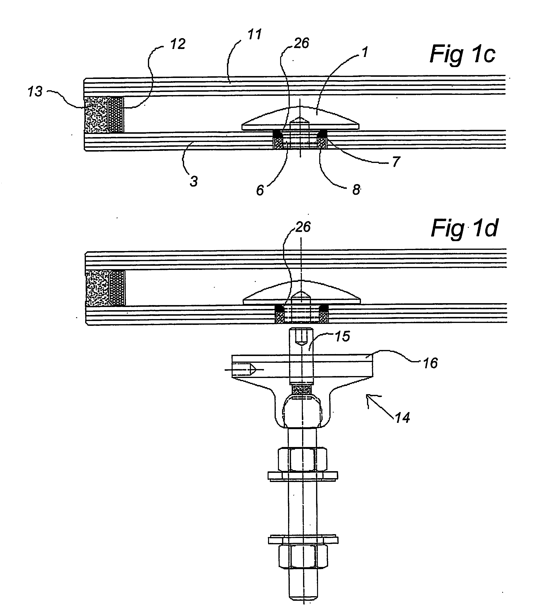
[0019]To assemble a glass element in accordance with the present invention an internal clamping plate 1 made from stainless steel is initially inserted in a hole 2 formed in an inner glass slab 3, see FIG. 1a. The clamping plate 1 is provided with tape 4 with an adhesive on both sides in such a manner that channels 5 form extending up to the outer edge of the clamping plate 1, from a connector part 6 located in the centre of the clamping plate 1. Around the connector part 6 are arranged two sealing rings 7 made from butyl and a synthetic-resin member 8. The synthetic-resin member 8 centres the connector part 6 in the aperture 2 in the glass slab 3.

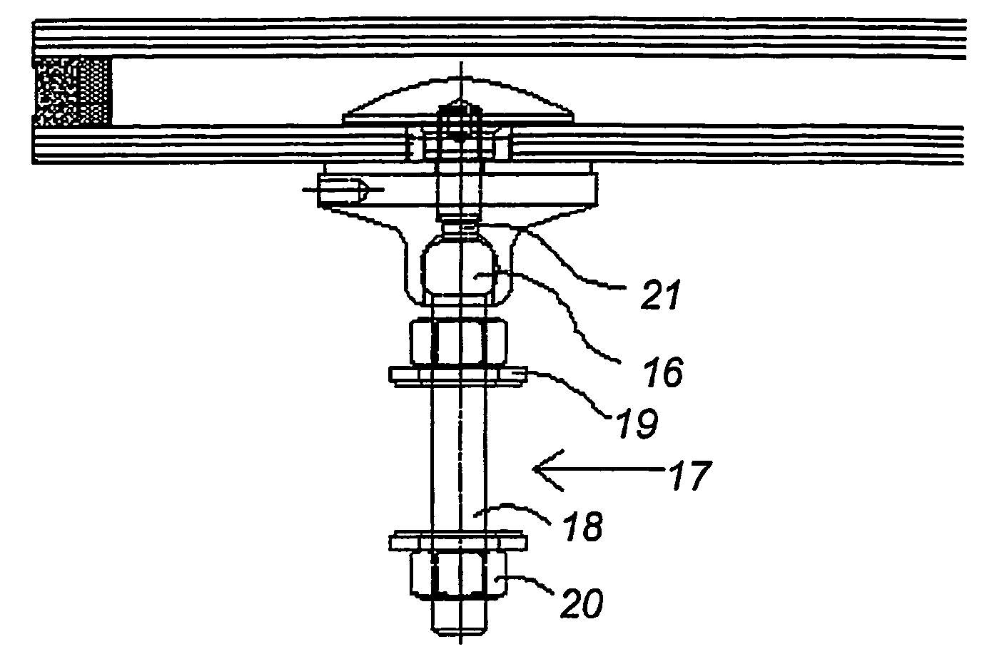
[0020]FIG. 1b shows the inner clamping plate 1 together with sealing rings 7 and the synthetic-resin member 8 in a partial cross-sectional view. A tool 9 is inserted into the connector part 6 in the clamping plate 1 in such a manner that an annular abutment element 10 forces the synthetic-resin member 8 inwards to ensure that the sealing r...


PUM

PropertyMeasurementUnit
Pressureaaaaaaaaaa
Flow rateaaaaaaaaaa

Abstract

A glass element includes at least two glass slabs arranged in facing relationship with a peripheral spacer frame arranged between each pair of glass slabs, and holders for anchorage at selective points to a supporting structure. The holders, each one of which includes two clamping plates joined together via connectors, are mounted exclusively in apertures formed in the glass element slab that faces the supporting structure, i.e. the inner glass slab. One of the clamping plates of each holder fitting is formed with anchorage attachment points that are accessible from the outside, and the inner clamping plates are placed in abutment against the inner face of the inner glass slab prior to the assembly of the inner glass slab and the next glass slab, in such a manner that their connecting parts extend at most up to the outer mouth of the apertures. The connecting parts of the outer clamping plates, which outer clamping parts are applied to the external face of the inner glass slab in a later step, engage the connecting parts of the inner clamping plates and form the attachment points. Seals are arranged in said apertures in the inner glass slab and the inner clamping plates are attached to the inner face of the inner glass slab.

Description

TECHNICAL FIELD OF THE INVENTION[0001]The present invention relates to a glass element comprising at least two glass slabs arranged in facing relationship with a peripheral spacer frame arranged between each pair of glass slabs, and holders for anchorage at selective points to a supporting structure, said holders, each one of which comprises two clamping plates which are joined together via connectors, being mounted exclusively in apertures formed in the glass element slab that faces the supporting structure, i.e. the inner glass slab, one of the clamping plates of each holder fitting being formed with anchorage attachment points that are accessible from the outside, and wherein the inner clamping plates are placed in abutment against the inner face of the inner glass slab prior to the assembly of said inner glass slab and the next glass slab, in such a manner that their connecting parts extend at most up to the outer mouth of the apertures, and that the connecting parts of the oute...

Claims


Application Information

Patent Timeline
IPC IPC(8): E06B3/54
CPCE06B3/5436Y10T29/49947Y10T29/49948E06B3/5445
Inventor STENVALL, BO
Owner VIDA INT AB
Why Eureka
Try Eureka