Supercharge Your Innovation With Domain-Expert AI Agents!

Flow Control Valve and Method

a flow control and valve body technology, applied in the direction of valve housings, positive displacement liquid engines, wellbore/well accessories, etc., can solve the problems of frequent failure of seals, shortening the life of o-rings, and accelerating wear of o-ring seats

Active Publication Date: 2008-03-06
SCHLUMBERGER TECH CORP
View PDF13 Cites 16 Cited by
  • Summary
  • Abstract
  • Description
  • Claims
  • Application Information

AI Technical Summary

Benefits of technology

The solution enhances the reliability and longevity of fluid flow control by reducing wear on seals, preventing plugging, and maintaining high pumping efficiency with reduced pressure loss, thus extending the lifespan of downhole tool valves.

Problems solved by technology

Since this fluid (e.g., formation fluid and / or borehole fluid) is often laden with impurities varying from fine mud particles to abrasive debris of various sorts, such flow can and often does produce accelerated wear of the O-ring seats.
This wear can shorten the life of the O-rings, and lead to frequent failure of the seals.
The following are examples of failures that may occur: 1) the o-ring is gradually worn during the pumping process until it will no longer seal; 2) debris (anything from LCM to heavy oil) gets trapped between the ball and one or both of the O-ring seats; 3) fine particles settle out in the valve cavity, and gradually build up to the point where they will prevent the ball from being able to seal against the seat; and 4) filters that are typically used with such valves are susceptible to plugging.
The failure of any one of the four reversible mud check valve seals typically reduces the output of pump 392 down to about half, and the loss of two seals may completely disable the pump.

Method used


Image

  • Flow Control Valve and Method
  • Flow Control Valve and Method
  • Flow Control Valve and Method

Examples


Embodiment Construction

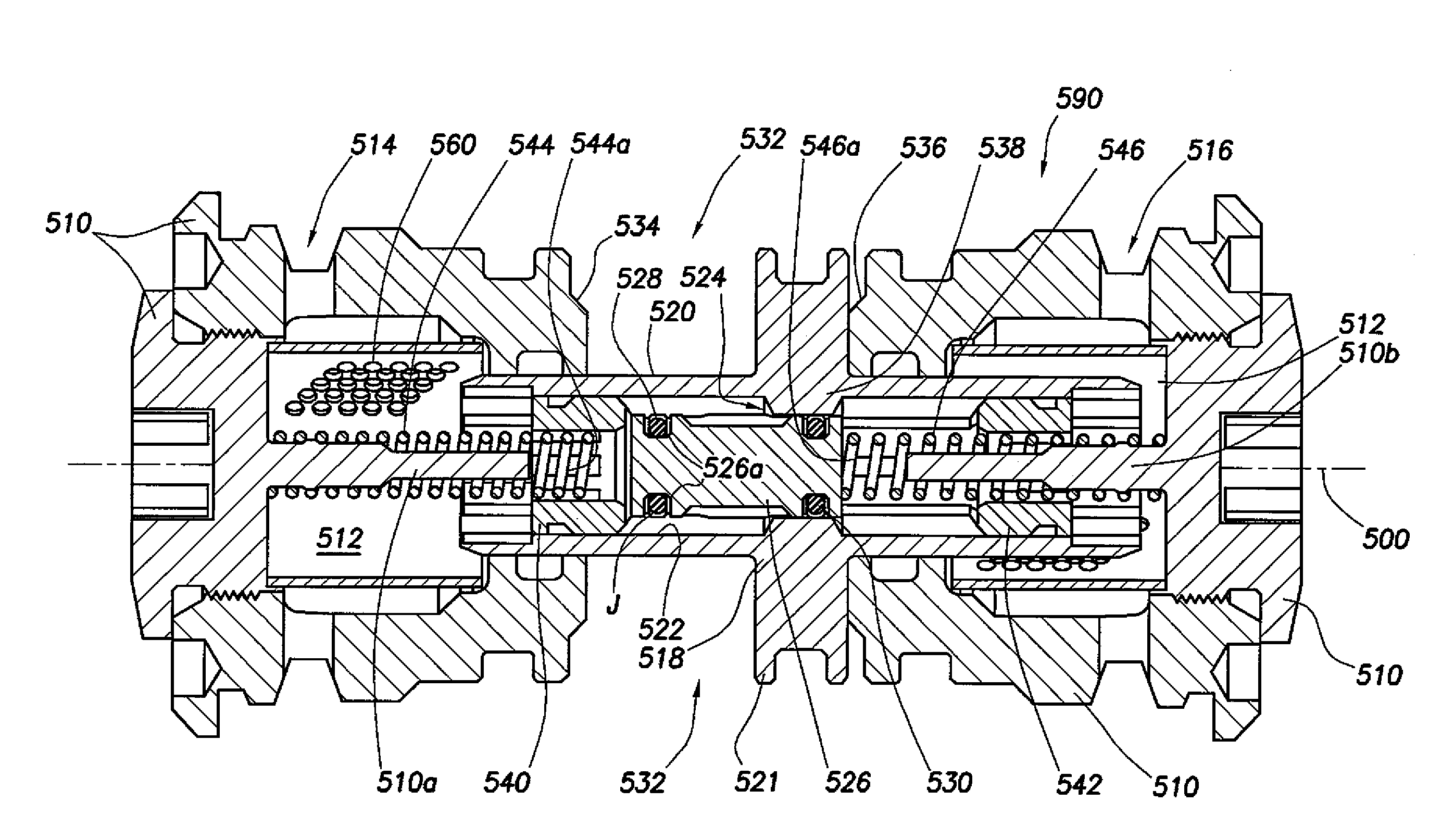
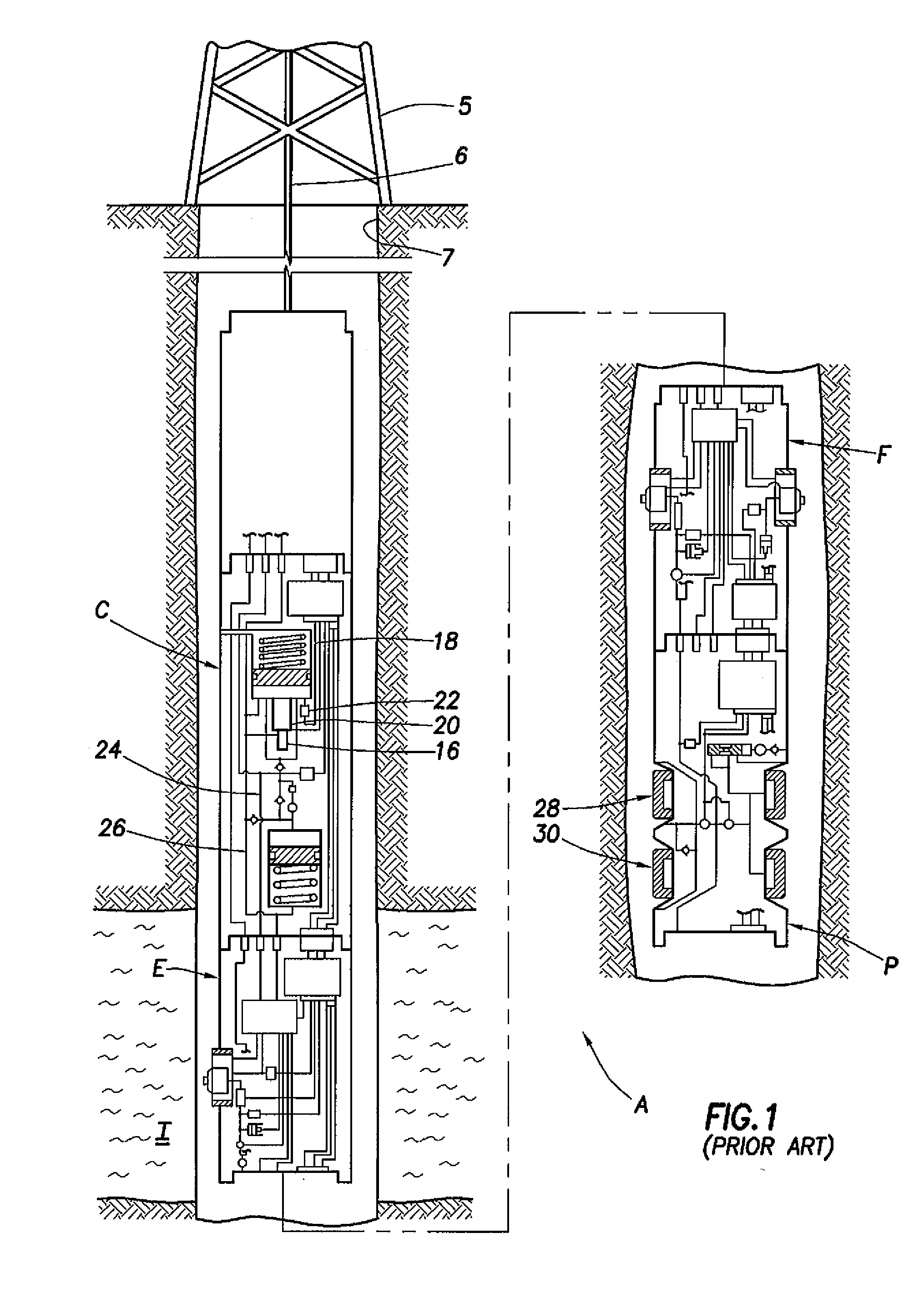
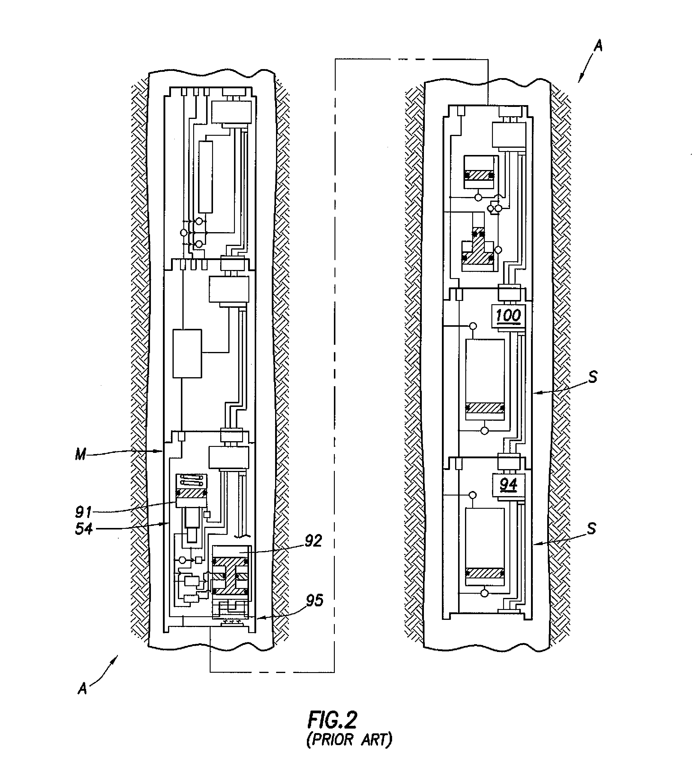
[0030] FIGS. 5A-B illustrate an inventive flow control valve 590 in respective closed and open positions. The valve 590 may be used to advantage as a check valve, e.g., as a replacement for check valve CMV1 (also referenced as 390) of FIGS. 3-4 within a downhole tool (see, e.g., tool A of FIGS. 1-2) adapted for use in a borehole environment. Accordingly, the check valve 590 includes a body 510 having a fluid passageway512 therethrough and first and second openings 514, 516 each adapted for receiving or discharging fluid from the passageway 512.

[0031] A piston 518 is slidably disposed in the passageway 512 between the first and second openings 514, 516 of the body 510. The piston 518 has a conduit portion 520 that defines a bore 522 therethrough for conducting fluid through a portion of the passageway 512. The bore 522 has a reduced flow area 524 (described further below). Components such as piston 518 are also referred to in the relevant art as a sliding cylinder, a check valve sli...


PUM


Abstract

A method for controlling fluid flow through a passageway includes slidably disposing a piston having a conduit that reduces the flow area through the passageway in the passageway and selectively closing the conduit of the piston by moving at least one of the piston and a plug.

Description

RELATED APPLICATION DATA [0001] This application is a divisional application of co-pending U.S. patent application Ser. No. 10 / 904,400, filed Nov. 8, 2004, the content of which is incorporated herein by reference for all purposes.BACKGROUND OF THE INVENTION [0002] 1. Field of the Invention [0003] The present invention relates to fluid flow control, and more particularly to valves for use in controlling the flow of fluid such as formation fluid and / or borehole fluid within a downhole tool. [0004] 2. Background of the Related Art [0005]FIGS. 1 and 2 illustrate a prior art downhole tool A which can be suspended from a rig 5 by a wireline 6 and lowered into a well bore 7 for the purpose of evaluating surrounding formations I. Details relating to apparatus A are described in U.S. Pat. Nos. 4,860,581 and 4,936,139, both assigned to Schlumberger, the entire contents of which are hereby incorporated by reference. The downhole tool A has a hydraulic power module C, a packer module P, and a p...

Claims


Application Information

Patent Timeline
Patent Type & Authority Applications(United States)
IPC IPC(8): E21B49/10
CPCE21B49/081F04B47/00F16K1/12F04B53/10F04B47/08Y10T137/778Y10T137/7771Y10T137/5196
Inventor BRENNAN, WILLIAM E. IIIHARRIGAN, EDWARDDEL CAMPO, CHRISTOPHER S.
Owner SCHLUMBERGER TECH CORP
Features
  • R&D
  • Intellectual Property
  • Life Sciences
  • Materials
  • Tech Scout
  • Unparalleled Data Quality
  • Higher Quality Content
  • 60% Fewer Hallucinations
Learn More