Handrail for a travelator, escalator or moving ramp and methods for mounting a handrail belt on a handrail and removing from a handrail

Inactive Publication Date: 2008-03-06
KONE CORP
View PDF7 Cites 0 Cited by
  • Summary
  • Abstract
  • Description
  • Claims
  • Application Information

AI Technical Summary

Benefits of technology

[0008] A further object of the invention is to disclose a handrail wherein the handrail belt undergoes little wear and has a long service life.
[0014] The invention has the advantage that, as the tensioning of the handrail belt is accomplished by moving the turn-around guide in the area of the end turn-around portions, the handrail belt only has to bend in its natural bending direction and with a large radius in the end turn-around portions in the area of the turn-around guides and no other bendings or counter-bendings are needed at all for the tensioning, so the handrail belt has a long service life due to reduced wear. The handrail belt can be easily and quickly mounted and removed.

Problems solved by technology

A problem with this prior-art tensioning is that the tensioning wheels required for the tensioning and the turn-around portions bending the handrail belt in different directions and the like take up plenty of space in the frame structures, which is why they are not suited for use in a travelator, moving ramp or escalator designed to be mounted on a base, in which the frame structure should be as low as possible.
In addition, bendings of the handrail belt in places other than the end turn-around portion as well as counter-bendings in a different direction than in the end turn-around portion increase the wear of the handrail belt and greatly reduce its service life.
Furthermore, in the case of prior-art handrails, mounting and removing the handrail belt is difficult and time-consuming.

Method used


Image

  • Handrail for a travelator, escalator or moving ramp and methods for mounting a handrail belt on a handrail and removing from a handrail
  • Handrail for a travelator, escalator or moving ramp and methods for mounting a handrail belt on a handrail and removing from a handrail
  • Handrail for a travelator, escalator or moving ramp and methods for mounting a handrail belt on a handrail and removing from a handrail

Examples


Embodiment Construction

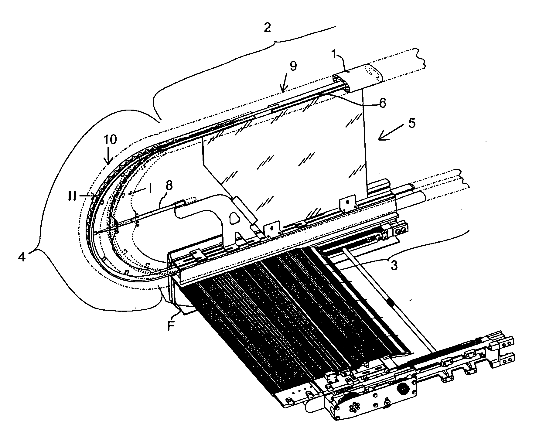
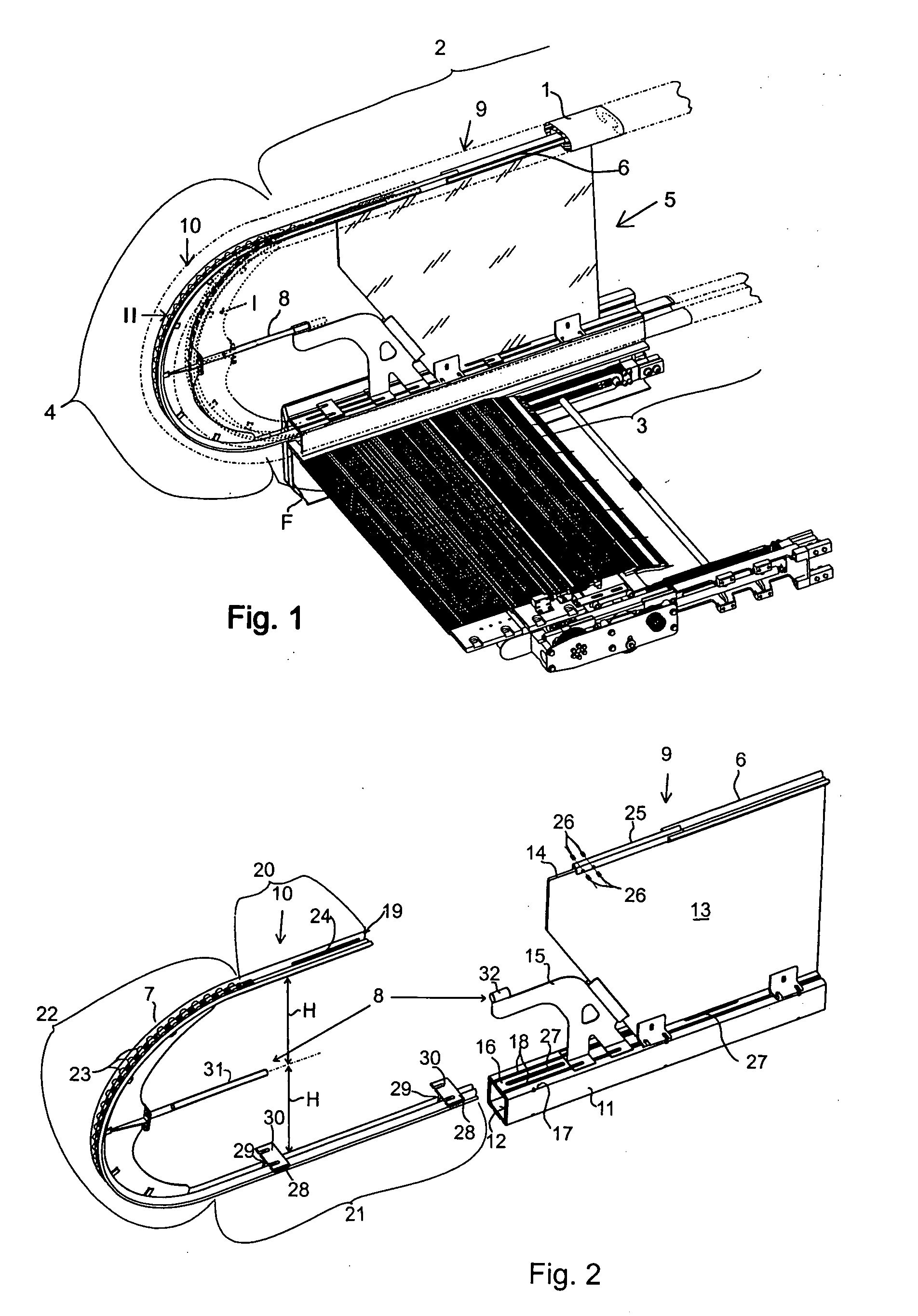
[0029]FIG. 1 shows a diagrammatic view of part of the end of a travelator, moving ramp or escalator and a handrail placed on one side of it. The handrail comprises a handrail belt 1, which has been arranged to move as an endless loop. In FIG. 1, part of the handrail belt is depicted in outline with dotted broken lines. The handrail belt 1 has an upper handhold portion 2, which the passenger on the travelator can grasp with a hand for support, and a lower return portion 3 and an end turn-around portion 4. In the end turn-around portion 4, the return portion 3 turns around with a 180° curvature to become the handhold portion 2, and vice versa.

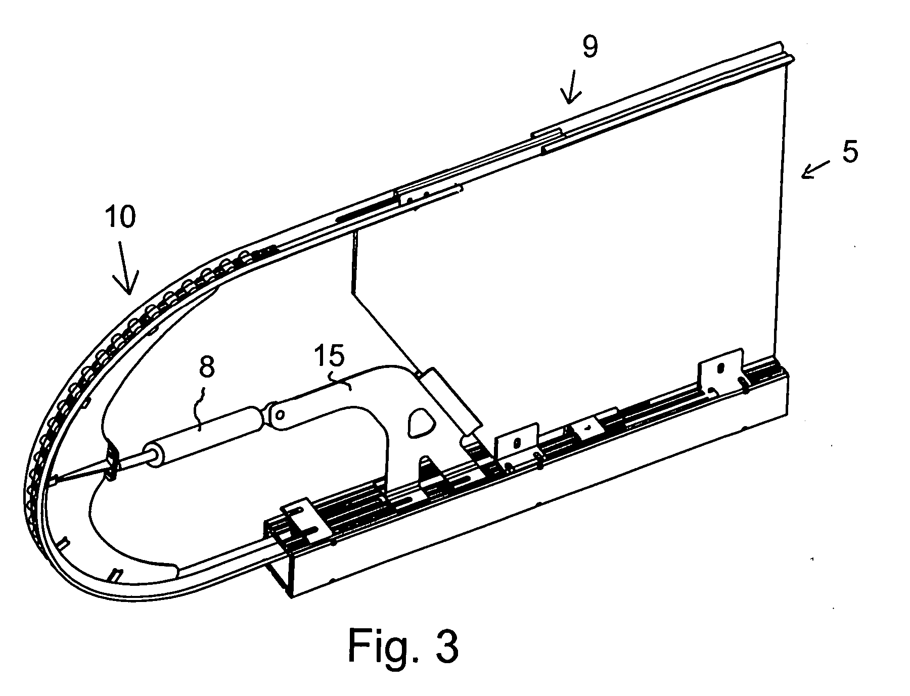
[0030] The handrail frame 5 is supported on the frame F of the travelator. The handrail frame 5 comprises an upper guide 6, which supports and guides the handhold portion 2 of the handrail belt loop. Further, the handrail frame 5 comprises a curved turn-around guide 7 to support and guide the end turn-around portion.

[0031] The handrail frame 5 ...


PUM


Abstract

A handrail for a travelator, moving ramp or escalator, wherein the handrail frame (5) of the handrail comprises a first handrail frame part (9) fixedly mounted on the frame of the travelator and a second handrail frame part (10) with a turn-around guide (7) connected to it, the second handrail frame part (10) being guided to be movable in the direction of the handrail with respect to the first handrail frame part (9) between a mounting position (I) and a tensioning position (II), in which mounting position (I) the handrail belt can be removed from the handrail and / or mounted on the handrail, and in which tensioning position (II) the handrail belt is in a tensioned state; and that a tensioning device (8) has been fitted to move the second handrail frame part (10) and to lock it in position relative to the first handrail frame part (9).

Description

FIELD OF THE INVENTION [0001] The present invention relates to a handrail as defined in the preamble of claim 1. Further, the invention relates to a method as defined in claim 12. In addition, the invention relates to a method as defined in claim 13. BACKGROUND OF THE INVENTION [0002] In prior art, a handrail for a travelator, moving ramp or escalator is known. Such a handrail comprises a handrail belt moving as an endless loop. The handrail belt is moved at a speed synchronized with the speed of motion of the conveyor of the travelator, moving ramp or escalator, so that a passenger on the travelator can grip the upper handhold portion of the handrail by hand for support. At the end of the handrail, the handrail belt is deflected on a turn-around portion through 180° to a return portion in the opposite return direction relative to the direction of motion of the upper handhold portion, the return portion being usually passed inside the frame structures to the other end of the travela...

Claims


Application Information

Patent Timeline
IPC IPC(8): B65G15/24B66BB66B23/20B66B23/24
CPCB66B23/24B66B23/20
Inventor AULANKO, ESKOMUSTALAHTI, JORMAOSSENDORF, MARC
Owner KONE CORP
Why Eureka
Try Eureka