Dispensing closure with obstructed, offset, non-linear flow profile

a technology of dispensing closures and obstructed openings, applied in the direction of closures using stoppers, caps, liquid handling, etc., can solve the problems of difficult manufacturing, more expensive than traditional one-piece dispensing closures, and a messy appearan

Active Publication Date: 2008-03-06
WESTROCK SLATERSVILLE
View PDF65 Cites 18 Cited by
  • Summary
  • Abstract
  • Description
  • Claims
  • Application Information

AI Technical Summary

Benefits of technology

[0010]The present invention preserves the advantages of existing dispensing closures while providing new advantages not found in currently available dispensing closures and overcoming many disadvantages of such currently available dispensing closures.
[0011]The general concept of the present invention is to provide a non-linear flow path from an interior of the dispensing closure to an exterior of the dispensing closure so that the product does not immediately spurt out upon opening of the closure lid and / or inverting and shaking the container to move the product toward the dispensing orifice.
[0014]In a first embodiment, the entrance orifice is a located in the side wall of the flow conduit, wherein the entrance axis is perpendicular to the exit axis. The bottom wall of the flow conduit thus prevents the direct flow of product into the flow conduit along the exit axis.
[0015]In another embodiment, the flow conduit is expanded to the side, and the entrance orifice is located in a bottom wall of the flow conduit but offset from the exit orifice. The entrance axis is parallel to but not co-linear with (i.e. offset) the exit orifice. Again, the bottom wall of the flow conduit thus prevents the direct flow of product into the flow conduit along the exit axis.
[0017]It is therefore an object of the present invention to provide a one-piece low cost dispensing closure that does not include a valve structure.

Problems solved by technology

Past dispensing closures tended to leak product onto the top deck of the closure after dispensing, creating a messy appearance and often requiring cleaning to reseal the closure.
While these silicone valves have been widely accepted by both the manufacturers and the consumers, they are somewhat more difficult to manufacture, as they require several inter-fitting parts, and thus they tend to be more expensive than traditional one-piece dispensing closures.
Another perceived drawback to the silicone valve closure is that they are constructed out of two different types of plastic and thus, from a recycling standpoint, they are more difficult to recycle because the silicone valve must be separated from the plastic closure body for recycling.
While this is not a major issue in the United States, at least yet, it is currently a major issue in Europe where recycling is extremely important and even mandated in some countries.
While the concept of the design may provide the desired flow characteristics, the design is virtually impossible to mold using conventional injection molding or blow molding techniques and thus is not commercially feasible.
While the circuitous path of this design is effective for water, the flow characteristics of water are different than other viscous fluids and thus the design is not believed to be suited for other more viscous products.
In short, it would be difficult to force viscous fluids through the multi-chamber design.

Method used


Image

  • Dispensing closure with obstructed, offset, non-linear flow profile
  • Dispensing closure with obstructed, offset, non-linear flow profile
  • Dispensing closure with obstructed, offset, non-linear flow profile

Examples


first embodiment

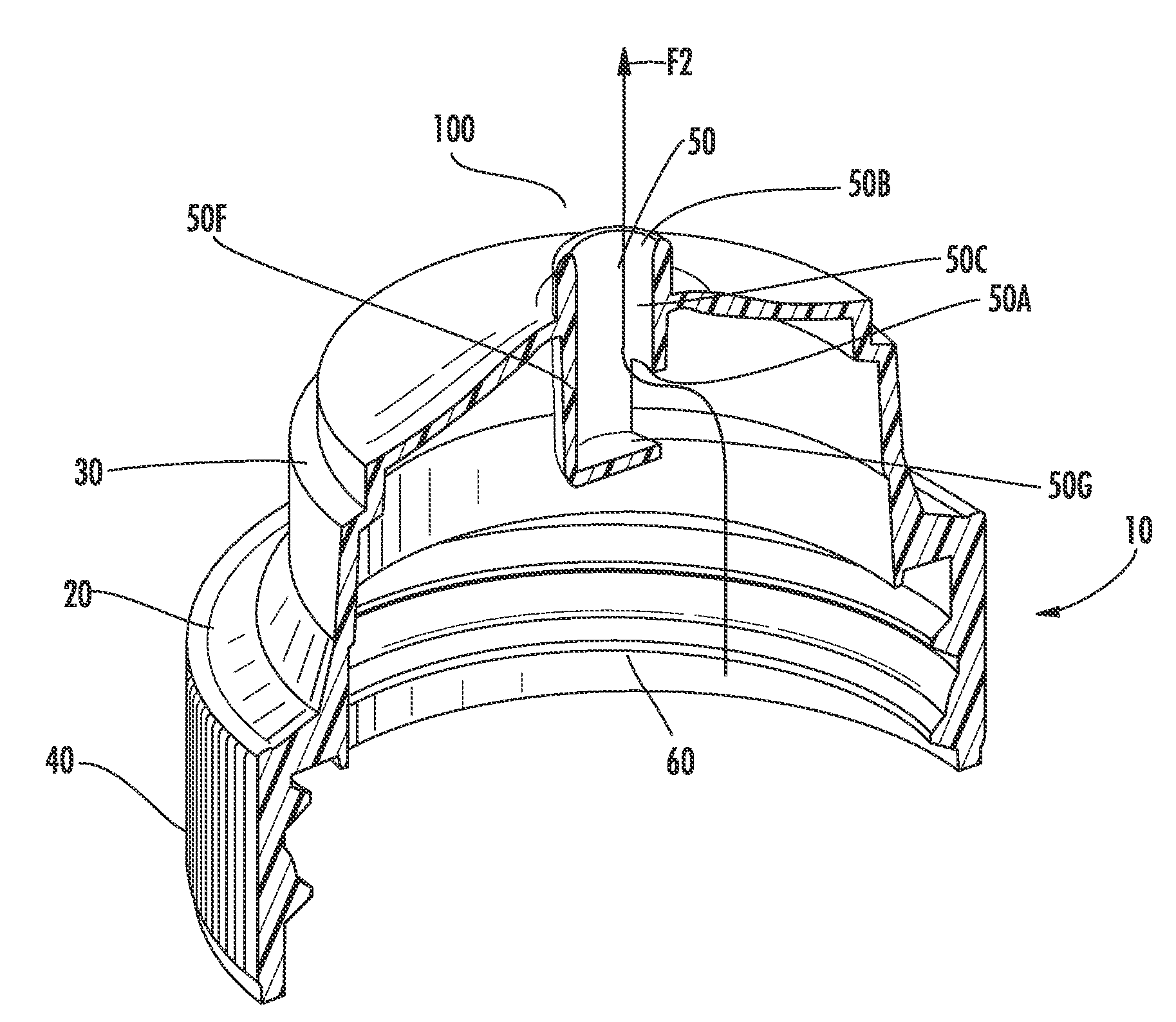
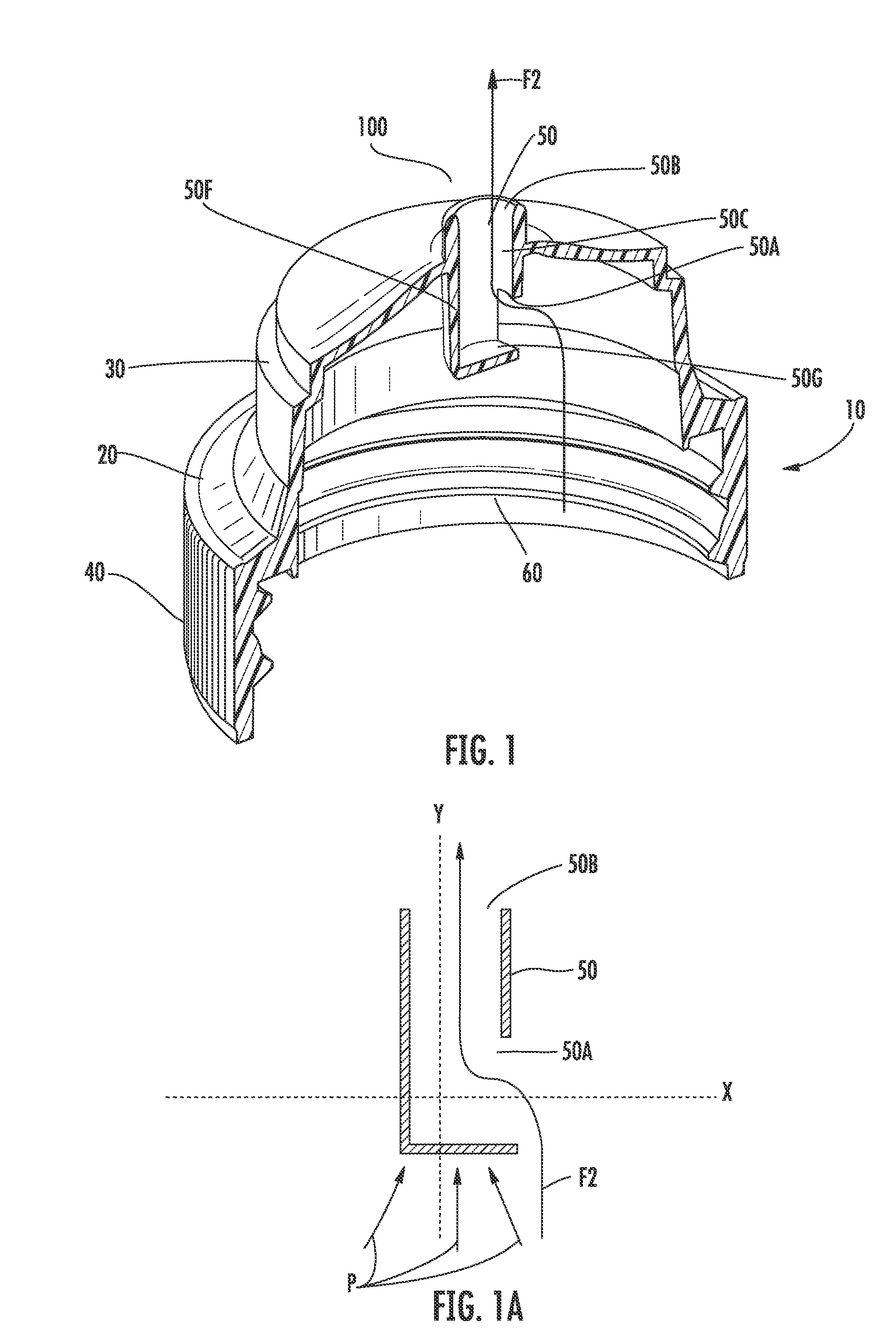
[0036]In the first embodiment as illustrated in FIGS. 1 and 1A, the entrance orifice 50A is located in the side-wall of the flow conduit 10, wherein the entrance axis X is perpendicular to the exit axis Y. The bottom wall 50G of the conduit thus prevents the direct flow of product (see arrows P—FIG. 1A) into the flow conduit along the exit axis Y and acts as a baffle to counter product head pressure created by either storing the product in an inverted condition, or head pressure created when an upright container is quickly inverted to dispense product. Flow of the product is shown by arrow F2.

[0037]The baffling effect is also enhanced by the passage of the product from the container, through the small entrance orifice 50A and into the interior of the flow conduit 50. The velocity of the product will increase as it travels through the entrance orifice 50A. However, the velocity of the product then decreases as it travels into the larger interior volume of the flow conduit 50 before i...

third embodiment

[0041]Now referring to FIGS. 3-6, the dispensing closure is illustrated and generally indicated at 10B. As mentioned previously, the embodiment of the dispensing closure 10B has a closure lid 130 attached to the closure body 20 of the dispensing closure. A living hinge structure 140 is used to connect the closure lid 130 and the closure body 20 to control the movement of the closure lid 130.

[0042]The flow conduit 50 includes a suspended central disc 110, which forms a bottom wall of the conduit. The central disc 110 is suspended within the flow conduit 50 by four downwardly depending arms (120 A-D), each distal end of the depending arms (120A-D) being attached to the central disc 110 and each proximal end of the depending arms (120A-D) being attached to the interior wall 50C of the flow conduit 50.

[0043]In a preferred embodiment, the four depending arms (120A-D) are equally spaced around an outer edge of the central disc 110. Alternatively, more than four arms or less than four depe...


PUM


Abstract

A dispensing closure has a flow conduit that provides a sufficient flow restriction to prevent unwanted spurting of the product when the container is initially opened. The dispensing closure includes a closure body with an upper deck and a flow conduit extending through the upper deck. The flow conduit includes an entry orifice having an entrance axis and an exit orifice having an exit axis. The entrance axis is offset from the exit axis to provide a non-linear flow path from an interior of the closure to the exterior of the closure.

Description

CROSS REFERENCE TO RELATED APPLICATION[0001]This application is related to and claims priority from provisional patent application Ser. No. 60 / 893,883 filed Mar. 8, 2007 and earlier filed provisional patent application Ser. No. 60 / 824,322 filed Sep. 1, 2006 both of which are incorporated herein by reference.BACKGROUND OF THE INVENTION[0002]The present invention relates to container closures, and more particularly to squeeze-type container dispensing closures.[0003]There are two major trends occurring in the design of dispensing containers and closures. The first trend is a focus on providing a “clean pour” during dispensing of the product. Many food products, such as mustard and ketchup, have a high viscosity and require the user to tip the container, shake down the product and then squeeze the container to dispense the product. Past dispensing closures tended to leak product onto the top deck of the closure after dispensing, creating a messy appearance and often requiring cleaning ...

Claims


Application Information

Patent Timeline
Patent Type & Authority Applications(United States)
IPC IPC(8): B67D3/00
CPCB65D47/0828B65D47/043B65D2547/063
Inventor SKILLIN, CLIFFORD W.ROMANOV, SERGEYBRANNON, PATRICK J.
Owner WESTROCK SLATERSVILLE
Why Eureka
Try Eureka