Document sorting machine

Inactive Publication Date: 2008-03-06
DE LA RUE INT LTD
View PDF30 Cites 22 Cited by
  • Summary
  • Abstract
  • Description
  • Claims
  • Application Information

AI Technical Summary

Benefits of technology

[0065] These aspects provide a flexible method of sorting a stack of notes that ar

Problems solved by technology

In addition, however, a lightly soiled documen

Method used


Image

  • Document sorting machine
  • Document sorting machine
  • Document sorting machine

Examples


Embodiment Construction

[0109] Embodiments of the abovementioned aspects of the invention will now be described with reference to the abovementioned drawings.

Overview

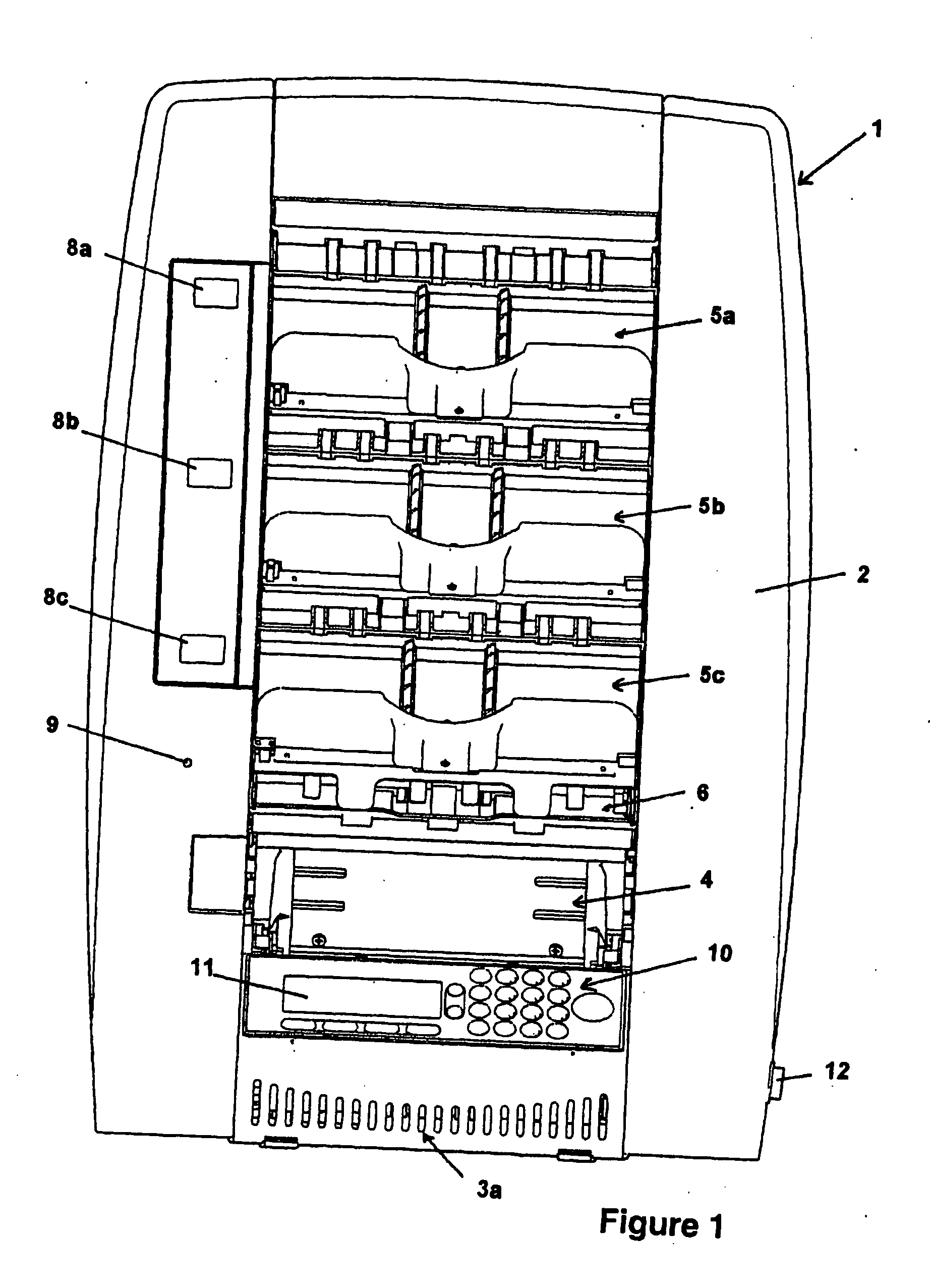
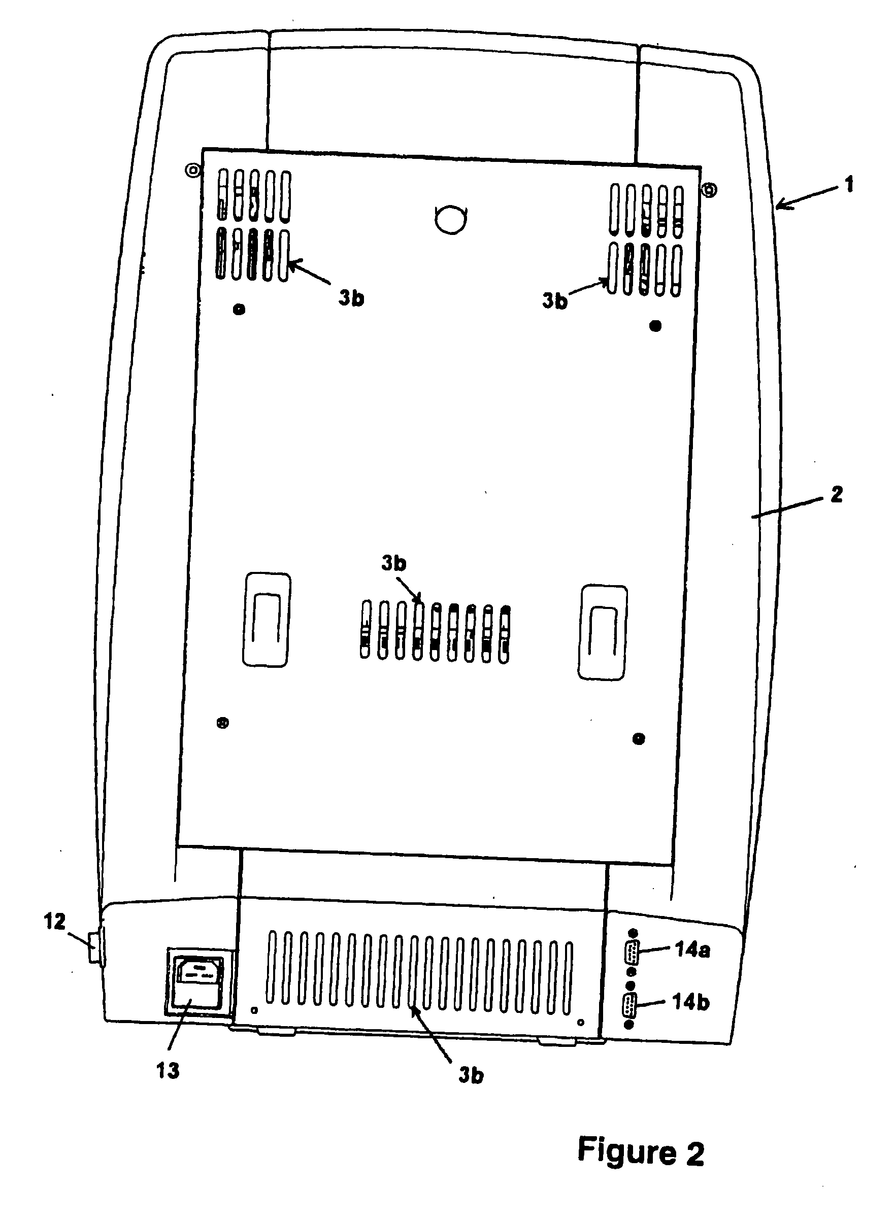
[0110]FIGS. 1, 2, 3 and 4 show the banknote sorting machine 1 in front, rear, left hand side and right hand side elevational views respectively.

[0111] It can be seen from the front elevational view of FIG. 1 that the banknote sorter 1 is enclosed within a casing 2 that is injection moulded from acrylonitrile butadiene styrene (ABS) . An array of ventilation holes 3a is provided towards the bottom of the casing to allow passage of air into the banknote sorter 1 in order to prevent it from overheating. The array of ventilation holes 3a works in conjunction with the arrays of ventilation holes 3b,3c and 3d which can be seen in FIGS. 2 to 4 provided in the rear, left hand side and right hand side of the casing of the banknote sorter 1 respectively. Banknotes are stacked on the base of a hopper that is part of the feeder system 4, which will be...


PUM

PropertyMeasurementUnit
Volumeaaaaaaaaaa
Volumeaaaaaaaaaa
Volumeaaaaaaaaaa

Abstract

A document feeder system for use in a document sorting apparatus is disclosed. The document feeder system comprises upper and lower portions, each having respective feeder elements for feeding documents from a hopper, the upper and lower portions being movable relative to one another between, a feeding position, in which the feeder elements of the upper and lower portions are engageable with a document to be fed, and a jam clearance position, in which a document between the feeder elements of the upper and lower portions may be retrieved, wherein the upper and lower portions are urged into the feeding position by a constant force spring.

Description

[0001] This is a Divisional of application Ser. No. 11 / 628,200 which is the U.S. National Stage of PCT / GB2005 / 002190 filed Jun. 6, 2005 and which claims the benefit of U.S. Provisional Applications No. 60 / 576,629 filed Jun. 4, 2004 and No. 60 / 631,160 filed Nov. 29, 2004. The disclosure of each prior application is hereby incorporated by reference herein in its entirety.INTRODUCTION [0002] This invention relates to a machine for sorting documents, and in particular banknotes. The banknotes are placed in a feeder at the bottom of the machine and fed via a transport through a detector system which measures one or more characteristics of the banknotes and these characteristics are used to decide which of a plurality of diverters to operate so as to divert the banknotes into the correct output pockets. Any banknotes that are not diverted by one of the diverters are fed into a cull pocket. [0003] The banknotes may be sorted on any one of a plurality of characteristics, for example, curren...

Claims


Application Information

Patent Timeline
IPC IPC(8): B65H43/02B07C5/34B65H1/06B65H3/06B65H5/00B65H7/00B65H15/00B65H29/60B65H33/14B65H39/10G07D11/00
CPCB65H1/06B65H3/063G07D11/0084G07D7/00B65H2701/1912B65H2601/325B65H2601/11B65H2557/24B65H2553/41B65H2513/42B65H2511/515B65H2511/51B65H2511/414B65H2511/30B65H2511/216B65H2511/212B65H2511/20B65H2408/111B65H2407/20B65H2402/547B65H2402/441B65H3/0669B65H5/00B65H7/00B65H15/00B65H29/60B65H33/14B65H39/10B65H2301/16B65H2301/33214B65H2301/33216B65H2301/424B65H2220/02B65H2220/01B65H2220/03G07D11/50B65H15/004B65H2402/54
Inventor CALVERLEY, SIMONSKINNER, JOHN ALANHOSKING, STEVEN MICHAELLEONARD, ANTONY JOHN
Owner DE LA RUE INT LTD
Why Eureka
Try Eureka