Floor display system with interactive features and variable image rotation

a technology of interactive features and display systems, applied in static indicating devices, audible signalling systems, instruments, etc., can solve problems such as difficulties in effectively and efficiently communicating, and difficulties in presenting problems relating to image orientation

Inactive Publication Date: 2008-03-06
COLLIN PEEL
View PDF99 Cites 37 Cited by
  • Summary
  • Abstract
  • Description
  • Claims
  • Application Information

AI Technical Summary

Problems solved by technology

Such an advertising medium is limited, however, by the fact that the message is static and not easily changed.
However, there remain challenges to effectively and efficiently communicating to an audience by displayed visual advertising or messaging on the floor or ground.
Among these challenges is how to orient the content of a display for easy viewing and comprehension.
On the other hand, when an image is in horizontal space, problems relating to the orientation of the image may be presented.
This image will be upside down and therefore largely unintelligible to viewers walking south.
Such considerations may be further complicated by observing how differences in language affect image presentation.

Method used


Image

  • Floor display system with interactive features and variable image rotation
  • Floor display system with interactive features and variable image rotation
  • Floor display system with interactive features and variable image rotation

Examples


Embodiment Construction

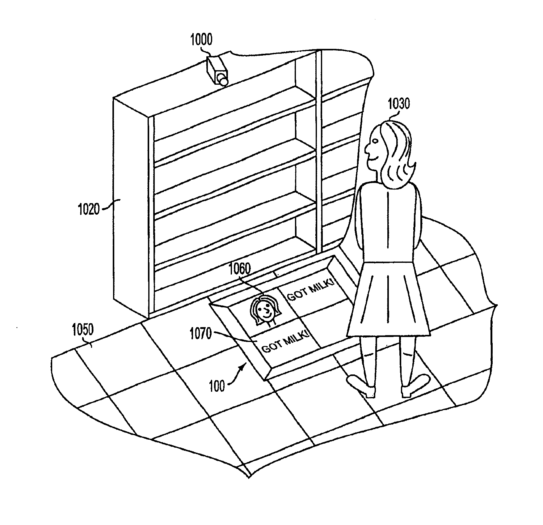
[0027] Embodiments of the present invention relate to a floor display system with, among other features, variable image orientation. More specifically, an image displayed by the floor display system may be oriented and / or reoriented depending on the perspective of viewers, in order to make the image more easily seen and understood. To orient and / or re-orient the image, the image may be rotated or otherwise moved or shifted.

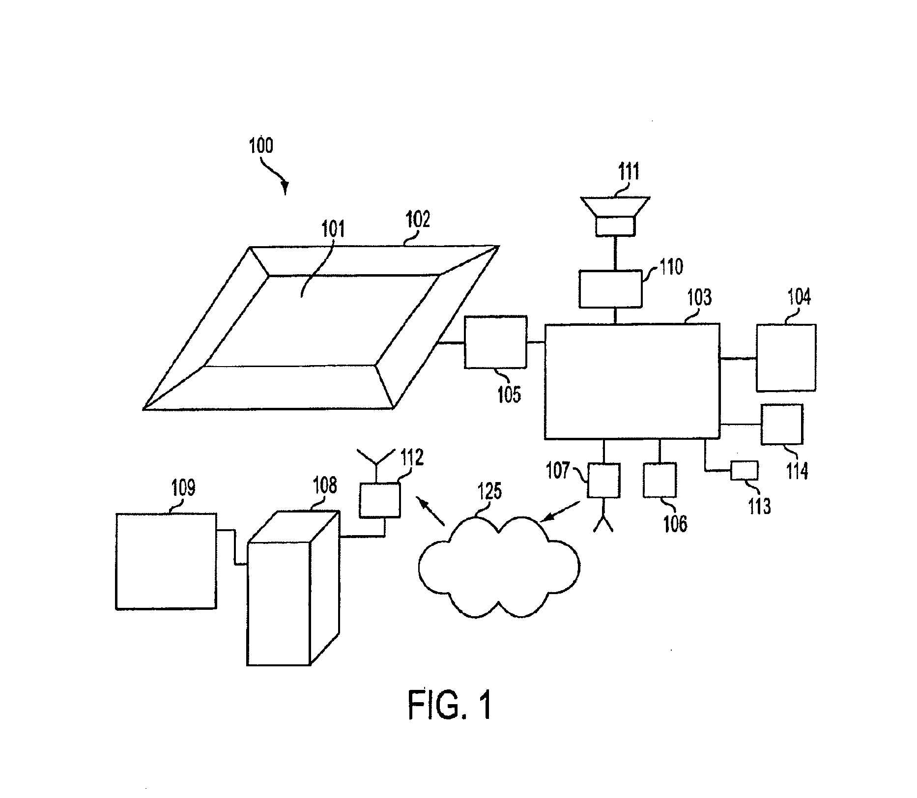
[0028] The floor display system may be arranged in a public place, such as a commercial establishment or other public building, and be configured to display electronically modifiable arbitrary content, such as advertising or other informational content. In embodiments, the floor display system may be configured to detect an indication of the presence or activity of a person in the vicinity, and upon detecting the indication, perform a corresponding action in response. For example, the floor display system may be arranged near shelving storing products for sale, a...


PUM


Abstract

Embodiments of the present invention relate to a floor display system with variable image orientation. Embodiments may further relate to networked data distribution and management; interactivity; image-enhancing optics; controlled audio; a protective covering; an anti-slip feature; fragrance technology; theft prevention; deployment in a track-and-trench system; specialized positioning mechanisms; and lightweight, flexible implementations.

Description

CROSS-REFERENCE TO RELATED APPLICATIONS [0001] This application is a continuation-in-part of commonly owned copending application Ser. No. 11 / 735,908, filed Apr. 16, 2007, which is a continuation-in-part of application Ser. No. 10 / 804,090, filed Mar. 19, 2004, which claims the benefit under 35 USC 119(e) of provisional application 60 / 457,115, filed Mar. 21, 2003 and of provisional application 60 / 460,353 filed Apr. 3, 2003, and which is a continuation-in-part of application Ser. No. 10 / 682,435, filed Oct. 10, 2003, and issued as U.S. Pat. No. 6,917,301 on Jul. 12, 2005, which is a continuation-in-part of application Ser. No. 10 / 438,923, filed May 16, 2003, and issued as U.S. Pat. No. 6,982,649 on Jan. 3, 2006, and claims the benefit of under 35 U.S.C. 119(e) of U.S. provisional applications identified as follows: application Ser. No. 60 / 418,626, filed Oct. 12, 2002; application Ser. No. 60 / 428,387, filed Nov. 21, 2002; and application Ser. No. 60 / 429,044, filed Nov. 22, 2003, applica...

Claims


Application Information

Patent Timeline
Patent Type & Authority Applications(United States)
IPC IPC(8): G08B5/00
CPCG06F3/041G06F3/1446G09F19/228G09G2380/06G09F19/22G06F3/011G06F3/0488
Inventor BLUM, RONALD D.KOKONASKI, WILLIAMTHIBODEAU, JOSEPH A.HARARI, BOAZKATZMAN, YOUVALGREENBERG, KOBBY
Owner COLLIN PEEL
Why Eureka
Try Eureka