Synchronous rectifier forward converter with reverse current suppressor

a reverse current suppressor and forward converter technology, applied in the direction of electric variable regulation, process and machine control, instruments, etc., can solve the problems of overvoltage of voltage spikes, potential risks, damage to power semiconductor devices within synchronous rectifiers, etc., and achieve the effect of simple circuit architecture and control mechanism

Active Publication Date: 2008-03-06
DELTA ELECTRONICS INC
View PDF7 Cites 22 Cited by
  • Summary
  • Abstract
  • Description
  • Claims
  • Application Information

AI Technical Summary

Benefits of technology

[0012]An object of the present invention is to provide a synchronous rectifier forward converter having a reverse current suppressor, in which the reverse current suppressor has a simple circuit architecture and control mechanism and does not need to be connected across the primary side and the secondary side of the transformer.

Problems solved by technology

Although the synchronous rectifier can provide several advantages such as low power loss and high conversion efficiency, some potential risks would occur at the instant of the start-up or the shutdown of the forward converter.
The major risk is caused by the reverse current which flows from the output capacitor Co to the secondary winding Ns.
These voltage spikes would damage the power semiconductor devices within the synchronous rectifier.
What is worse, the instantaneous voltage value of these voltage spikes would exceed the rated voltage of the power semiconductor devices and burn down the power semiconductor devices.

Method used


Image

  • Synchronous rectifier forward converter with reverse current suppressor
  • Synchronous rectifier forward converter with reverse current suppressor
  • Synchronous rectifier forward converter with reverse current suppressor

Examples


first embodiment

The First Embodiment

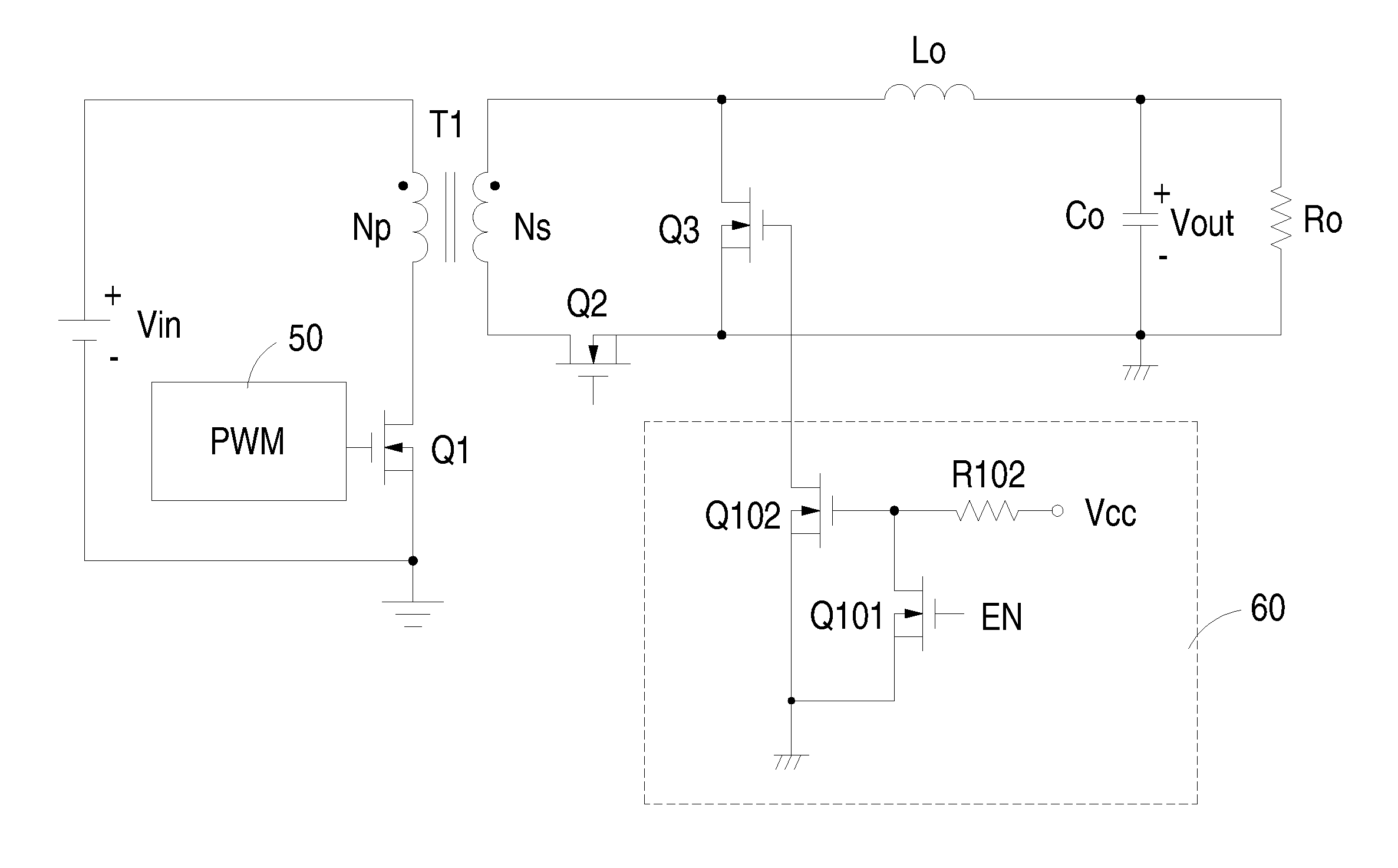
[0032]FIG. 5 is a waveform diagram illustrating the waveforms of the voltage employed in forward converter and the control input signal applied to the reverse current suppressor according to a first embodiment of the present invention. FIG. 6 is a circuit diagram illustrating the circuit architecture of the synchronous rectifier forward converter and the reverse current suppressor thereof according to the first embodiment of the present invention. In the present embodiment, the reverse current suppressor 60 is configured to receive a control input signal to determine if the converter is shut down. It is noteworthy that the phase of the trailing edge of the control input signal will lead the phase of the trailing edge of the output voltage which indicates the point of the interruption of the input power. As shown in FIG. 6, the control input signal is an enable signal EN which is issued by an internal circuitry of the power supply system where the synchronous rect...

second embodiment

The Second Embodiment

[0037]A second preferred embodiment of the present invention is illustrated in FIGS. 7 and 8. FIG. 7 shows the waveforms of the voltages and control signals employed in the synchronous rectifier forward converter and the reverse current suppressor thereof according to a second preferred embodiment of the present invention, and FIG. 8 shows a circuit diagram of the synchronous rectifier forward converter and the reverse current suppressor thereof according to a second preferred embodiment of the present invention. In the present embodiment, the reverse current suppressor 60 is configured to generate a voltage detection signal indicative of the voltage across the secondary side of the transformer to detect if a reverse current is generated. In FIG. 8, an input bulk capacitor Cb is connected across the primary side of the transformer and configured to provide an input DC voltage Vin to the forward converter so as to convert the input DC voltage Vin into a regulated...


PUM


Abstract

Disclosed is a synchronous forward converter having a reverse current suppressor connected to the gate of a freewheel switch. The reverse current suppressor is configured to receive a control input signal generated by an internal circuitry of a power supply system where the forward converter locates, such as an enable signal, to detect the power-off of the forward converter, and in response thereto turn off the freewheel switch during the interruption of the input power of the forward converter. Alternatively, the reverse current suppressor is configured to detect the decay of the input voltage across the input bulk capacitor located on the primary side of a transformer of the forward converter, and turn off the freewheel switch when the voltage across the secondary side of the transformer is decayed to be smaller than the output voltage of the forward converter.

Description

FIELD OF THE INVENTION[0001]The present invention is related to a synchronous rectifier forward converter, and more particularly to a synchronous rectifier forward converter with a reverse current suppressor, in which the reverse current suppressor is configured to timely turn off the freewheel switch located within the synchronous rectifier, so as to suppress the reverse current generated in the synchronous rectifier when the input voltage of the forward converter is interrupted due to the shutdown of the forward converter.BACKGROUND OF THE INVENTION[0002]In a typical forward converter, a main switch is placed on the primary side of the transformer and connected in series with the primary winding of the transformer, and a rectifier circuit which is made up of rectifying diodes is placed on the secondary side of the transformer. The magnetizing inductance of the primary winding of the transformer is configured to receive the current from the voltage input terminal of the forward con...

Claims


Application Information

Patent Timeline
Patent Type & Authority Applications(United States)
IPC IPC(8): H02M3/335
CPCY02B70/1475H02M3/33592Y02B70/10
Inventor WANG, KUAN-SHENGLIU, TIAN-HUA
Owner DELTA ELECTRONICS INC
Why Eureka
Try Eureka