Optical transmission apparatus having OADM function

a transmission apparatus and optical technology, applied in the field of optical transmission apparatuses, can solve the problems of inability to realize the oadm function, the number of the number of ports thereof, and the number of wirings which couple the wavelength selective switches (wsss) in a geometric series, so as to reduce the number of wirings, simplify the structure and size of the optical transmission apparatus, and simplify the effect of the structure and size of the optical transmission

Inactive Publication Date: 2008-03-06
FUJITSU LTD
View PDF4 Cites 46 Cited by
  • Summary
  • Abstract
  • Description
  • Claims
  • Application Information

AI Technical Summary

Benefits of technology

[0038]Another and more specific object of the present invention is to provide an optical transmission apparatus which can add signal light having an arbitrary wavelength with respect to an arbitrary signal add port and drop signal light having an arbitrary wavelength from an arbitrary signal drop port, using a considerably reduced number of expensive wavelength selective switches (WSSs) and considerably reduced number of wirings for coupling the wavelength selective switches (WSSs), so as to enable the structure and size of the optical transmission apparatus to be simplified and reduced, respectively, while enabling to easily cope with an increase or decrease of the number of routes and an increase or decrease of the number of wavelengths (that is, channels).
[0039]Still another object of the present invention is to provide an optical transmission apparatus comprising a first wavelength selective switch for route switching, provided with respect to each route, and configured to selectively output signal light from a first input route to second through Nth output routes and to selectively output signal lights from second through Nth input routes to a first output route, for every wavelength; a second wavelength selective switch for add and drop, configured to selectively output a signal light from an add port to the first through Nth output routes via the first wavelength selective switch for every wavelength, and to selectively output the signal lights from the first through Nth input routes to a drop port via the first wavelength selective switch for every wavelength; and an optical coupler configured to multiplex each of the signal lights output from the first wavelength selective switch to the output routes and each of the signal lights output from the second wavelength selective switch to the output routes, for every route, and to send multiplexed signal light to a first wavelength selective switch of an other route, and to branch and supply multiplexed signal light input from said other route to the first wavelength selective switch and the second wavelength selective switch, wherein the signal lights input and output by the first wavelength selective switch and the second wavelength selective switch are transmitted bidirectionally within a single optical transmission line. According to the optical transmission apparatus of the present invention, it is possible to add signal light having an arbitrary wavelength with respect to an arbitrary signal add port and drop signal light having an arbitrary wavelength from an arbitrary signal drop port, using a considerably reduced number of expensive wavelength selective switches (WSSs) and considerably reduced number of wirings for coupling the wavelength selective switches (WSSs), so as to enable the structure and size of the optical transmission apparatus to be simplified and reduced, respectively, while enabling to easily cope with an increase or decrease of the number of routes and an increase or decrease of the number of wavelengths (that is, channels).

Problems solved by technology

In other words, it is not possible to realize the OADM function with respect to arbitrary routes by an arbitrary signal add port and an arbitrary signal drop port.
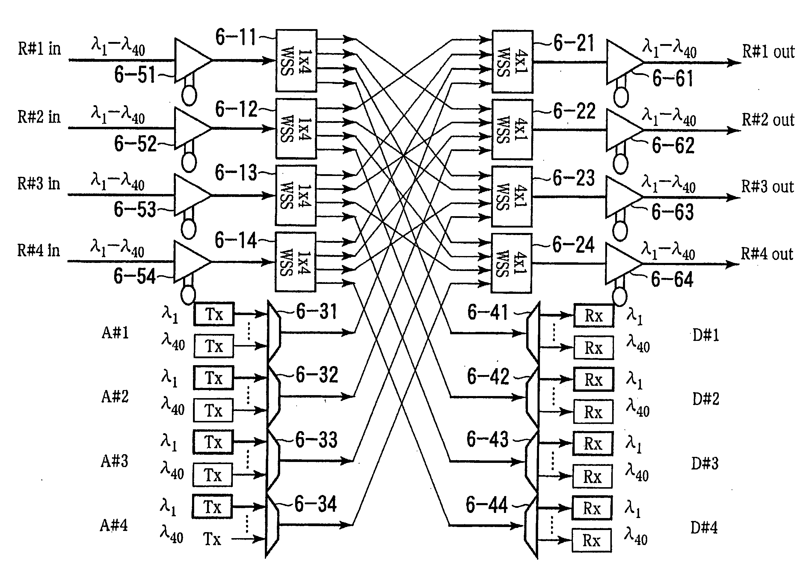
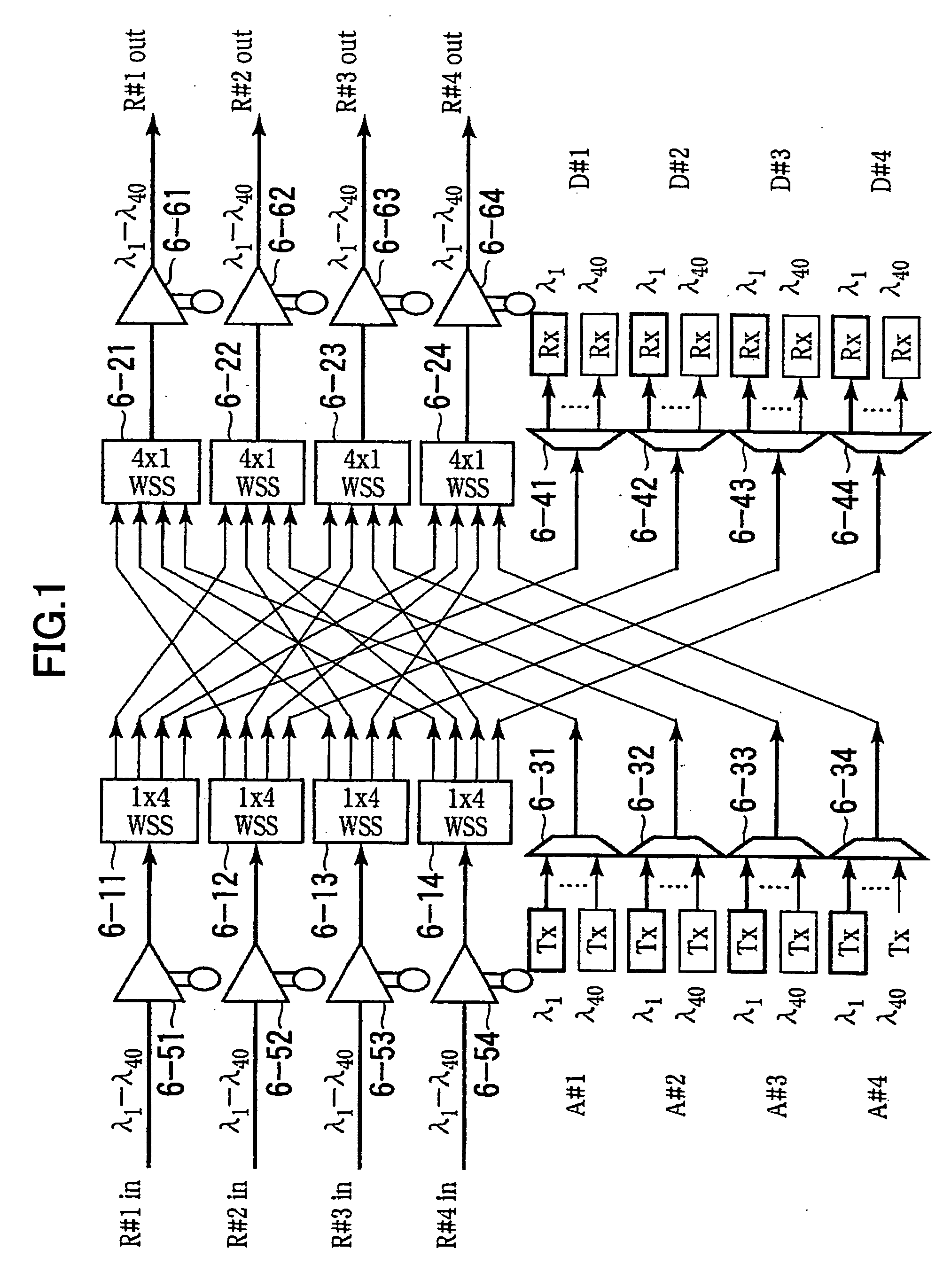
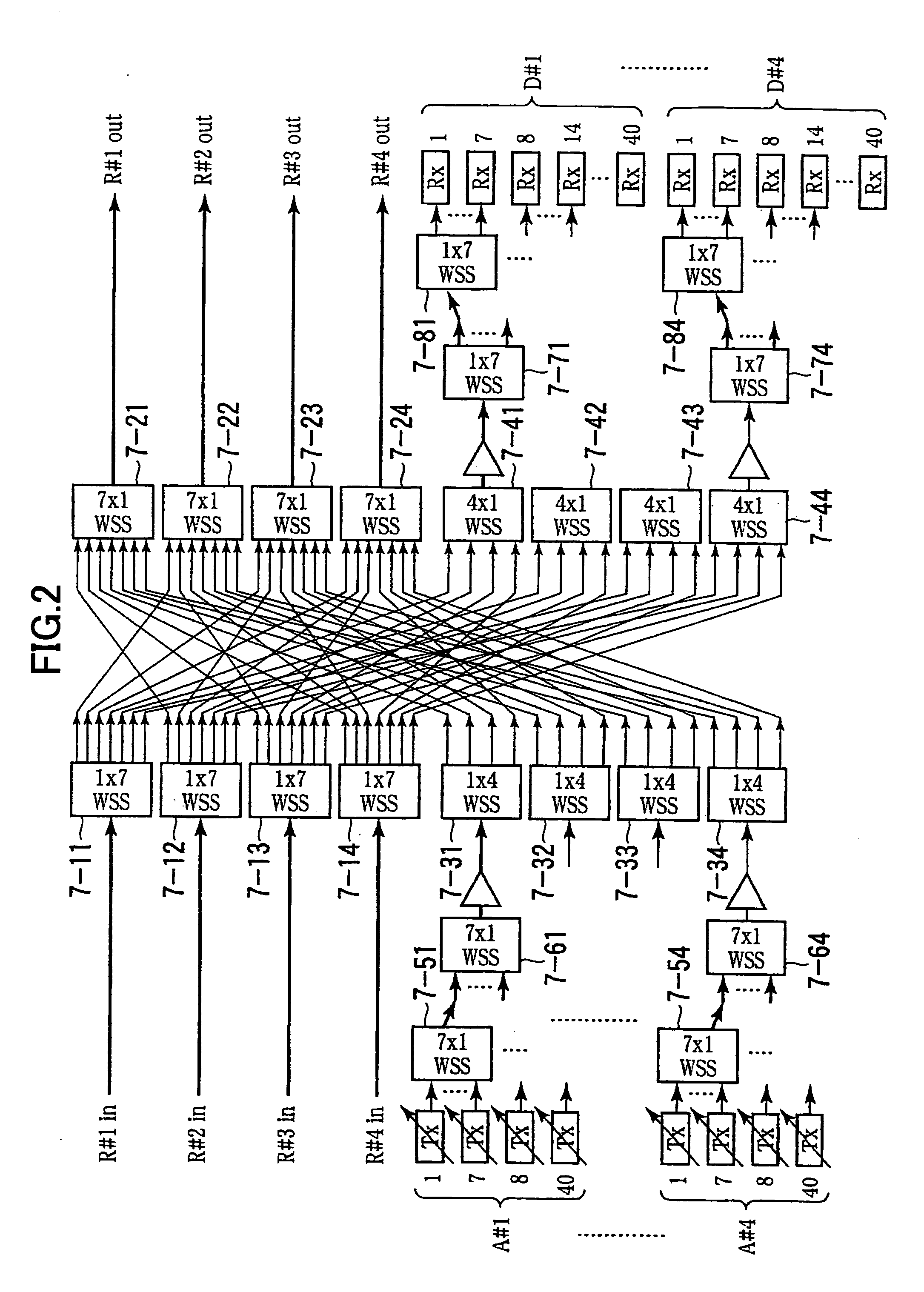
Therefore, according to the structure shown in FIG. 2, it is possible to add the signal light having an arbitrary wavelength with respect to an arbitrary signal add port and to drop the signal light having an arbitrary wavelength from an arbitrary signal drop port, but compared to the structure shown in FIG. 1, there were problems in that the number of required wavelength selective switches (WSSs) and the number of ports thereof increase considerably, that the number of wirings which couple the wavelength selective switches (WSSs) increases in a geometric series, and that the cost and the scale of the optical transmission apparatus increase.

Method used


Image

  • Optical transmission apparatus having OADM function
  • Optical transmission apparatus having OADM function
  • Optical transmission apparatus having OADM function

Examples


first embodiment

[0048]FIG. 3 is a system block diagram showing a structure of an optical transmission apparatus according to the present invention for a portion including 1 route R#1 and 1 add port A#1 and 1 drop port D#1. As shown in FIG. 3, a (1×N)-port wavelength selective switch (1×N_WSS) 1-1 for route switching is provided for selectively outputting the signal light from a first input route R#1in to second through Nth output routes R#2out through R#Nout, and for selectively outputting the signal lights from second through Nth input routes R#2in through R#Nin to a first output route R#1out for every wavelength.

[0049]In addition, a (1×N)-port wavelength selective switch (1×N_WSS) 1-2 for add and drop is provided for selectively outputting the signal light from a first add port A#1 to the first through Nth output routes R#1out through R#Nout for every wavelength, and for selectively outputting the signal lights from the first through Nth input routes R#1in through R#Nin to the first drop port D#1...

second embodiment

[0069]FIGS. 7 through 12 are diagrams for explaining differences in the performances of the optical transmission apparatus according to the present invention and the conceivable optical transmission apparatus. More particularly, FIGS. 7 through 12 show the performances of the first or second embodiment of the optical transmission apparatus shown in FIG. 4 or 6 and the conceivable optical transmission apparatus shown in FIG. 2. For the sake of convenience, FIGS. 7 through 12 show the route switching function and the add and drop functions with respect to the signal light for the first route R#1.

[0070]For example, a symbol “Δ” in a box at the intersection of the route switching function “R#1→R#2” for switching to another route and the add and drop functions “A#1→R#1, R#1→D#1” in FIG. 7 indicates that one of the route switching function “R#1→R#2” and the add and drop functions “A#1→R#1, R#1→D#1” is executable. The symbol “Δ” is used similarly in FIGS. 7 through 12.

[0071]In addition, a ...


PUM


Abstract

An optical transmission apparatus has a first wavelength selective switch (WSS) for route switching, provided with respect to each route, to selectively output signal light from a first input route to second through Nth output routes and to selectively output signal lights from second through Nth input routes to a first output route, for every wavelength, a second WSS for add and drop, to selectively output a signal light from an add port to the first through Nth output routes via the first WSS for every wavelength, and to selectively output the signal lights from the first through Nth input routes to a drop port via the first WSS for every wavelength, and an optical coupler to multiplex each of the signal lights output from the first WSS to the output routes and each of the signal lights output from the second WSS to the output routes, for every route, and to send multiplexed signal light to a first WSS of an other route, and to branch and supply multiplexed signal light input from said other route to the first WSS and the second WSS. The signal lights input and output by the first WSS and the second WSS are transmitted bidirectionally within a single optical transmission line.

Description

BACKGROUND OF THE INVENTION[0001]1. Field of the Invention[0002]The present invention generally relates to optical transmission apparatuses, and more particularly to an optical transmission apparatus that is for a wavelength division multiplex (WDM) optical transmission system, and is provided with a wavelength cross-connect (WXC) function and an optical add and drop multiplexing (OADM) function.[0003]2. Description of the Related Art[0004]The WDM optical transmission system is used in a trunk optical network that connects nodes, formed by optical transmission apparatuses set up in a city or the like, via optical transmission lines, and exchanges WDM signal light. The WXC function of the WDM optical transmission system switches an output destination route of signal light input from each route for every wavelength, and sends the signal light to a predetermined route. The OADM function of the WDM optical transmission system adds and sends signal light having an arbitrary wavelength to...

Claims


Application Information

Patent Timeline
Patent Type & Authority Applications(United States)
IPC IPC(8): H04J14/00H04B10/29H04B10/27H04B10/291H04J14/02H04L12/931H04Q3/52
CPCH04J14/0204H04J14/0205H04J14/0209H04J14/0212H04J14/0213H04Q2011/006H04J14/0217H04J14/0219H04Q11/0005H04Q2011/0035H04J14/0216
Inventor AKIYAMA, YUICHITERAHARA, TAKAFUMIOOI, HIROKI
Owner FUJITSU LTD
Why Eureka
Try Eureka