Magnetic levitation motor and method for manufacturing the same

a technology of magnetization and levitation motor, which is applied in the direction of mechanical energy handling, dynamo-electric components, mechanical apparatus, etc., can solve the problems of reduced critical speed, increased length of rotor shaft, and reduced motor siz

Inactive Publication Date: 2003-10-21
SANKYO SEIKI MFG CO LTD
View PDF6 Cites 19 Cited by
  • Summary
  • Abstract
  • Description
  • Claims
  • Application Information

AI Technical Summary

Benefits of technology

As a result, the segmented permanent magnets function as permanent magnets for generating a rotation force and magnets for generating a levitation force. Accordingly, the structure is simplified and reduced in size and the cost is reduced.
In one aspect of the embodiment of the present invention, the two rotors forming the two magnetic levitation motor sections are respectively formed from the segmented permanent magnets. The segmented permanent magnets are mounted on a common rotation member of a magnetic material at different locations in an axial direction of the common rotation member. Furthermore, the two magnetic levitation motor sections includes two stator cores that have an identical structure. A first stator winding and a second stator winding are wound around each of the two stator cores. As a result, the motor output can be increased, and the levitation force that is well balanced in the axial direction is obtained.
In one aspect of the embodiment of the present invention, surfaces of the segmented permanent magnets facing one of the stator cores have an N-pole and surfaces of the segmented permanent magnets facing the other of the stator cores have an S-pole. As a result, the segmented permanent magnets can function as both of permanent magnets for generating a rotation force and permanent magnets for generating a levitation force. As a consequence, the structure is simplified.
In one aspect of the embodiment of the present invention, opposing surfaces of the segmented permanent magnets that face the stator cores have an arc shape to make a gap magnetic flux density to have generally a sine waveform. As a result, mutual interference between the levitation force and the rotation force can be reduced, and the levitation force and the rotation force can be efficiently obtained.
Also, in one aspect of the embodiment of the present invention, the magnetic levitation motor has detecting sections that are integrally mounted on the common rotation member at locations that interpose the two magnetic levitation motor sections, and gap sensors opposing to the detecting sections. A current to the first stator winding for generating a levitation force is controlled such that gaps between the gape sensors and the detection sections detected by the gap sensors are constant. As a result, the common rotation member and the rotating parts including the rotor can be supported in a non-contact manner.
With the structure described above, the thrust magnetic bearing can also be incorporated as a compound structure and can be reduced in size. As a result, the length of the shaft can be shortened, and a higher rotation speed can be obtained.

Problems solved by technology

However, in this structure, the magnetic bearings are disposed on both sides of the motor section, and therefore the length of the rotor shaft increases, and the critical speed lowers.
This leads to various problems.
For example, the number of assembly steps increases, the size reduction of the motors becomes difficult, the manufacturing cost increases and the motors are restricted to a limited number of structures.
However, the magnetic levitation motor described in this reference is difficult to generate a large output appropriate for the overall size of the magnetic levitation motor.
The thrust magnetic bearing occupies a substantially large portion of the overall structure of the motor, and therefore is a hindrance to the size reduction of the magnetic levitation motors.

Method used


Image

  • Magnetic levitation motor and method for manufacturing the same
  • Magnetic levitation motor and method for manufacturing the same
  • Magnetic levitation motor and method for manufacturing the same

Examples


Embodiment Construction

Magnetic levitation motors in accordance with various embodiments of the present invention are described below with reference to the accompanying drawings.

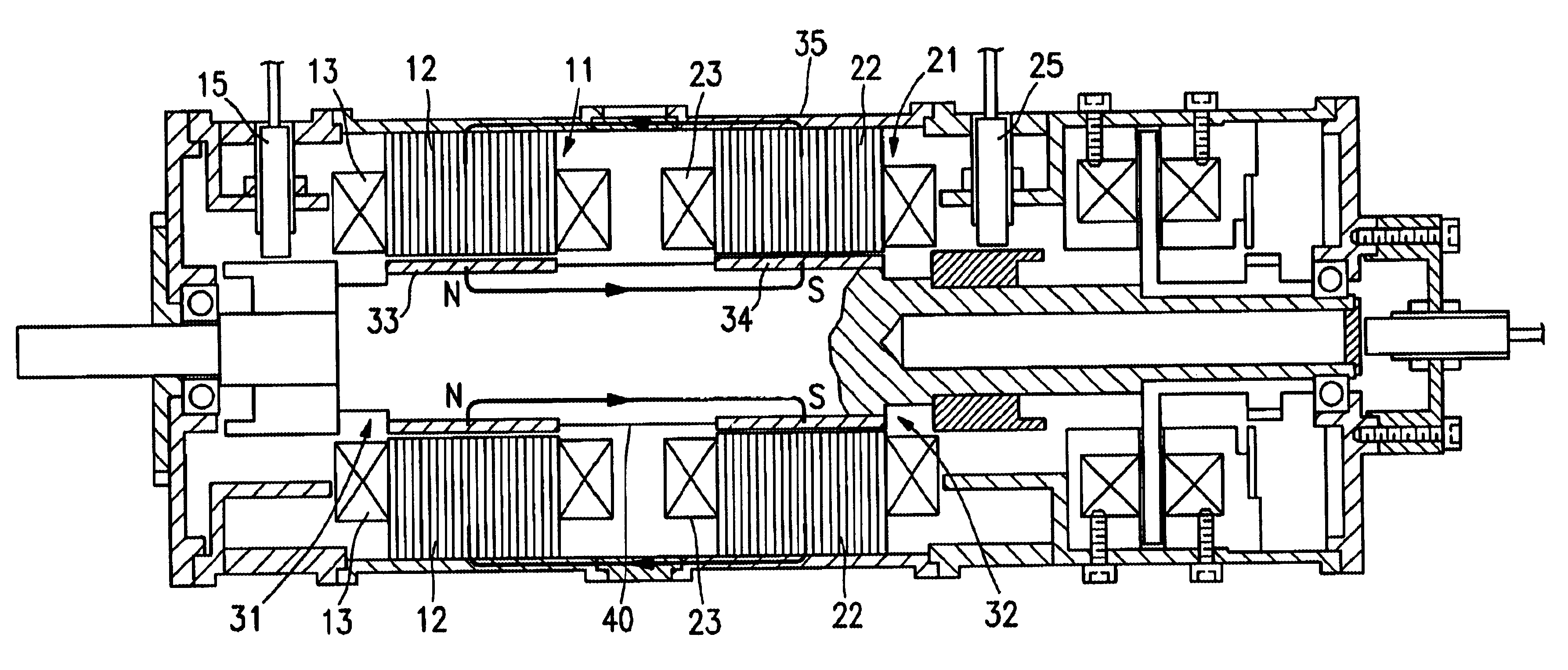
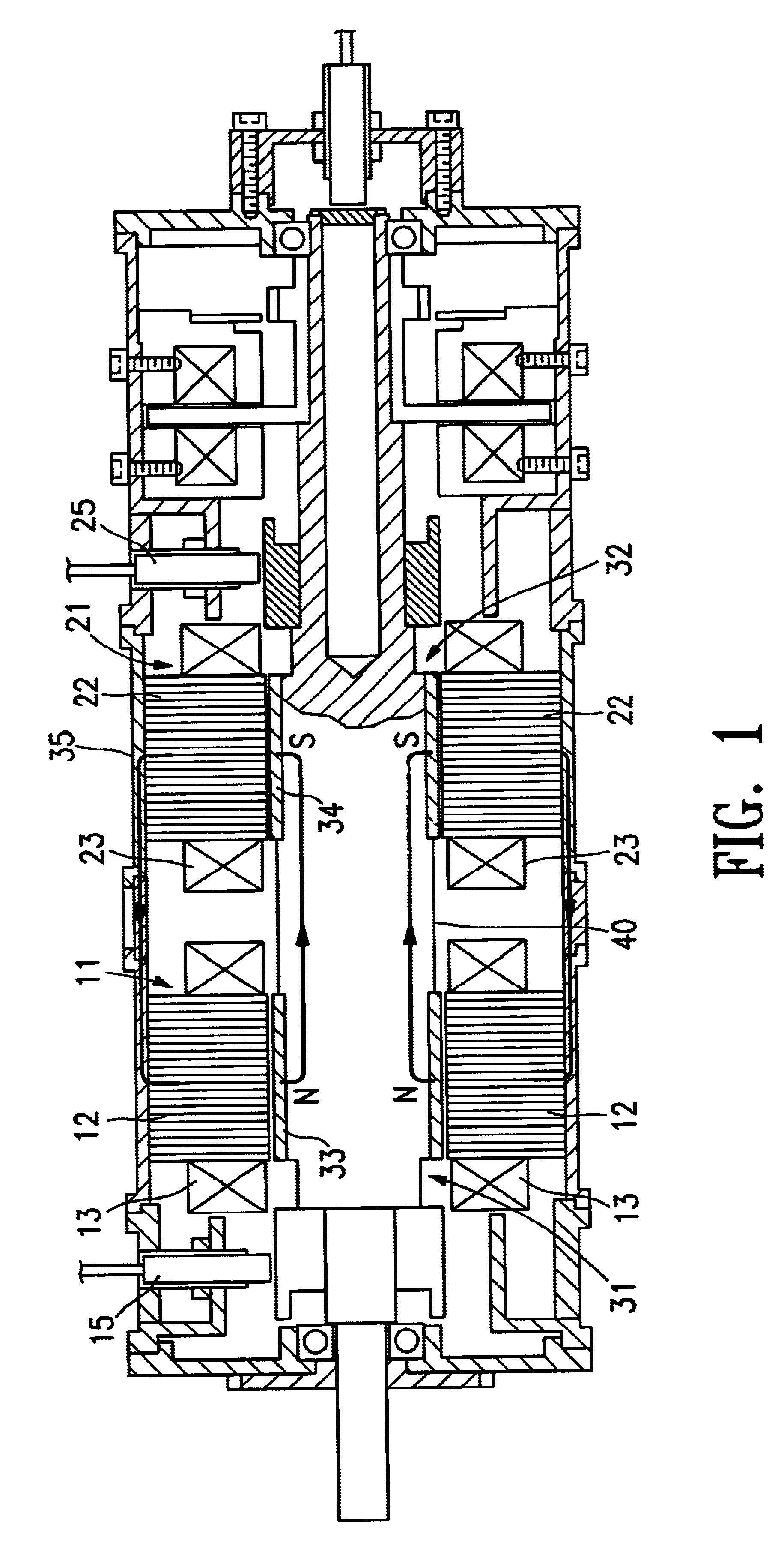
FIGS. 13 and 14 show a magnetic levitation motor 1 having rotors 2a and 2b, stators 3a and 3b, a direct current magnetic field generation device 4, first stator windings 5a and 5b for controlled levitation, a second stator winding 6 for generating a rotation force, and a plurality of permanent magnets 7 provided on the rotors. A motor is formed between the rotor 2a equipped with the permanent magnet 7 and the stator 3a. Also, magnetic bearings are formed between the rotors 2a and 2b and the stators 3a and 3b, respectively.

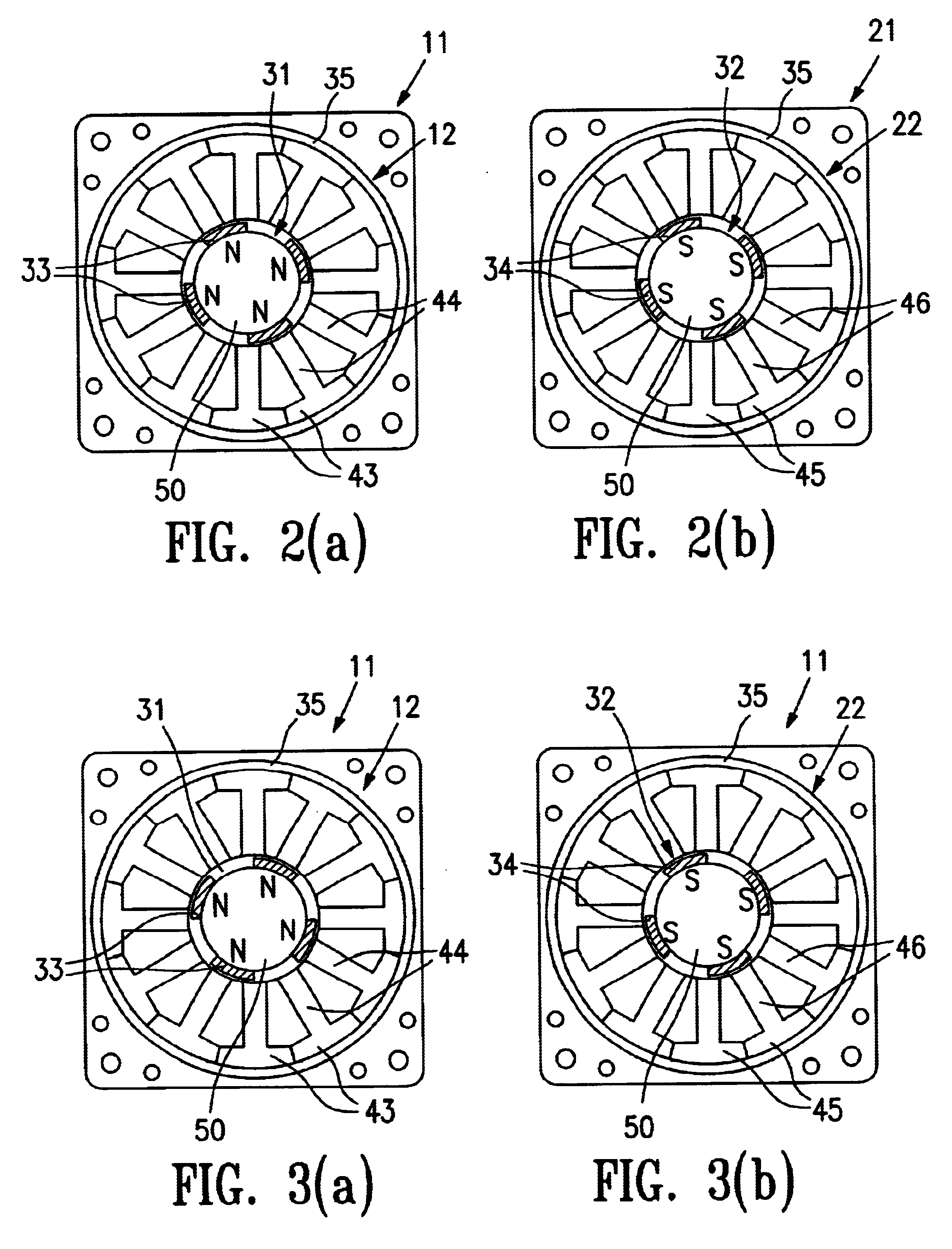
The rotors 2a and 2b are composed of a magnetic material, and provided on a rotor shaft 8 of a magnetic material at locations spaced a specified distance from one another. Among the rotors 2a and 2b, the plural permanent magnets 7 are disposed around a peripheral surface of the rotor 2a in a manner that their mag...


PUM


Abstract

A magnetic levitation motor has a rotator body formed from a magnetic member and having segmented permanent magnets attached to a peripheral surface thereof. Two magnetic levitation motor sections are disposed in an axial direction of the rotator body. Each of the magnetic levitation motor sections having a first stator winding that generates a levitation control magnetic flux for levitating the rotator body and a second stator winding that generates a rotation magnetic flux for rotating the rotator body. The segmented permanent magnets are affixed to the rotator body at the two magnetic levitation motor sections with magnetic polarities thereof mutually opposite to each other. The segmented permanent magnets function as bias magnets that generate a direct-current magnetic flux that radially spreads from within the rotor.

Description

1. Field of the InventionThe present invention relates to a magnetic levitation motor having a stator winding for controllably levitating a rotor and another stator winding for generating a rotation magnetic flux and a method for manufacturing the same.2. Description of Related ArtContact-type bearings are widely used. In addition, non-contact type magnetic bearings are also gaining popularity. A typical magnetic bearing uses a magnetic force to levitate a rotor member such as a rotor shaft and supports the rotor member in a non-contact manner. By the use of the magnetic bearing, the coefficient of friction of the bearing section becomes substantially zero (0), which makes a high-speed rotation possible. Also, the magnetic bearing does not need lubrication oil. This allows the use of the magnetic bearing under special conditions. For example, the magnetic bearing can be used at a high temperature or a low temperature, in vacuum and the like. Furthermore, no maintenance work is requi...

Claims


Application Information

Patent Timeline
Patent Type & Authority Patents(United States)
IPC IPC(8): H02K7/09F16C39/06
CPCH02K7/09F16C32/0493F16C2380/26
Inventor KANEBAKO, HIDEKIOKADA, YOHJI
Owner SANKYO SEIKI MFG CO LTD
Why Eureka
Try Eureka