
Gas converter

a technology of converters and gas, applied in the field of gas converters, can solve the problems of high labor costs, high construction cost, and high cost of materials

Inactive Publication Date: 2008-03-06
SNC-LAVALIN
View PDF4 Cites 7 Cited by
  • Summary
  • Abstract
  • Description
  • Claims
  • Application Information

AI Technical Summary

Problems solved by technology

Such structures are expensive to build due to the relatively high cost of materials, the complexity of welding stainless steel to maintain corrosion resistance, and the requirement of highly skilled labour often working in remote locations.
Since all internal components had to be corrosion resistant, construction of such grillage platforms was very expensive and led to curved plate supports as described in the above mentioned patents.
From such examples it will be appreciated that converters are highly variable in configuration with external and internal gas ducts, plenums and catalyst support platforms and heat exchangers combined to form a complex, large scale and expensive structure.
The opposite is also true that failure to fully consider the lifecycle costs of designing, manufacturing, construction and operation of a complex converter design can increase overall costs significantly.

Method used


Image

  • Gas converter
  • Gas converter
  • Gas converter

Examples


second embodiment

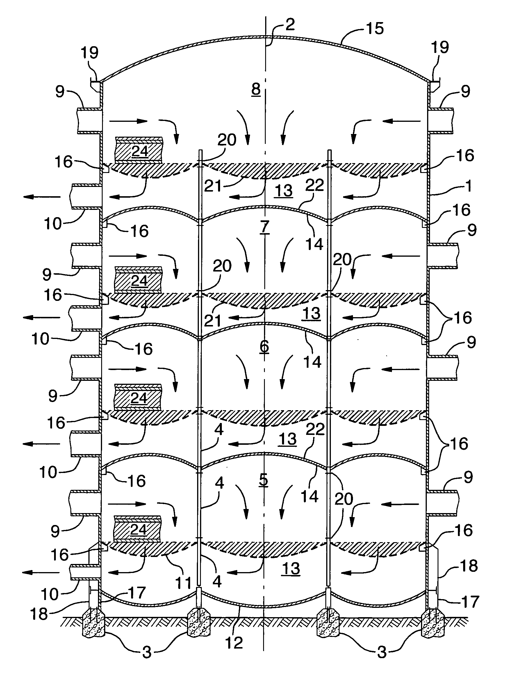
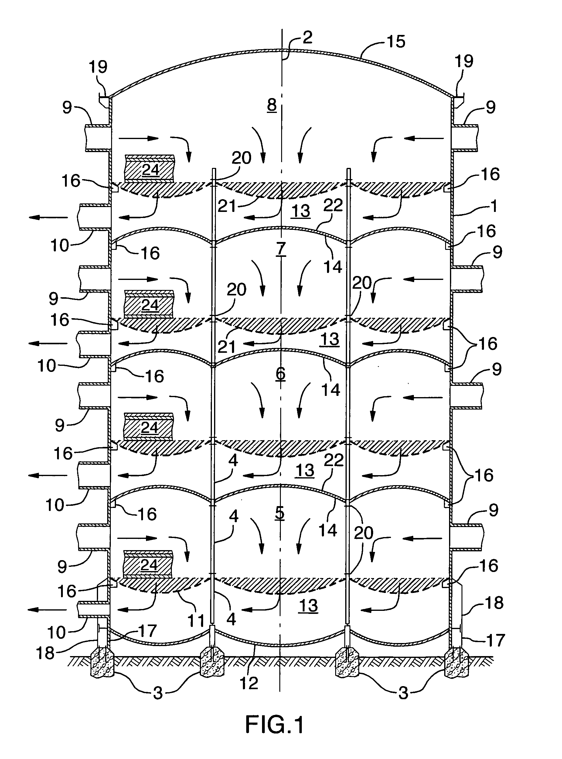
[0032]The second embodiment illustrated in FIG. 7 shows a conventional tube heat exchanger where a first flow path passes over the exterior surface of the vertical tubes 27 contained by top and bottom tube sheets 29 from a first inlet 30 to a first outlet 31. A second flow path through the interior of the tubes 27 is conveyed upwardly as drawn and communicates thermally through the tube walls with the gas flow in the first path. The second flow path through the primary heat exchanger 26 conveys gas from a second inlet 32 to a second outlet 33 such that the first outlet 31 outputs gas above the catalytic bed 24 of chamber 5 and after gas passes through the bed to the plenum 13 the second inlet 32 intakes gas from first pass chamber 5 and conveys the gas to second pass chamber 6 via the tubes 27 and outlet 33. Dilution inlet 36 is shown as an option to illustration the potential for ducting as required for various chemical or thermodynamic process steps. As a result, the combination o...

third embodiment

[0033]FIG. 8 illustrates a third embodiment where the cylindrical interior shell 28 extends the full height of the converter from the foundation piers 3 to the top division plate 15. An “interpass” or secondary heat exchanger 34 is provided with vertical tubes 27 conveying gas from an external duct 35 which communicates through the secondary heat exchanger 34 between the plenum 13 of the second pass catalytic chamber 6 and the third pass catalytic chamber 7 above the bed 24. The secondary heat exchanger 34 has a somewhat different set of flow paths and illustrates the variation possible while maintaining the compact design of the converter. A third flow path commences at a third inlet 37 passing through the interior of the tubes 27 to exit via an annular array of third outlets 38. The third outlets 38 output gas above the catalytic bed 24 of the third pass chamber 7. Gas then is collected in the plenum 13 and exits the converter via one or more outlets 39 for external processing if ...


PUM

PropertyMeasurementUnit
Pressureaaaaaaaaaa
Permeabilityaaaaaaaaaa

Abstract

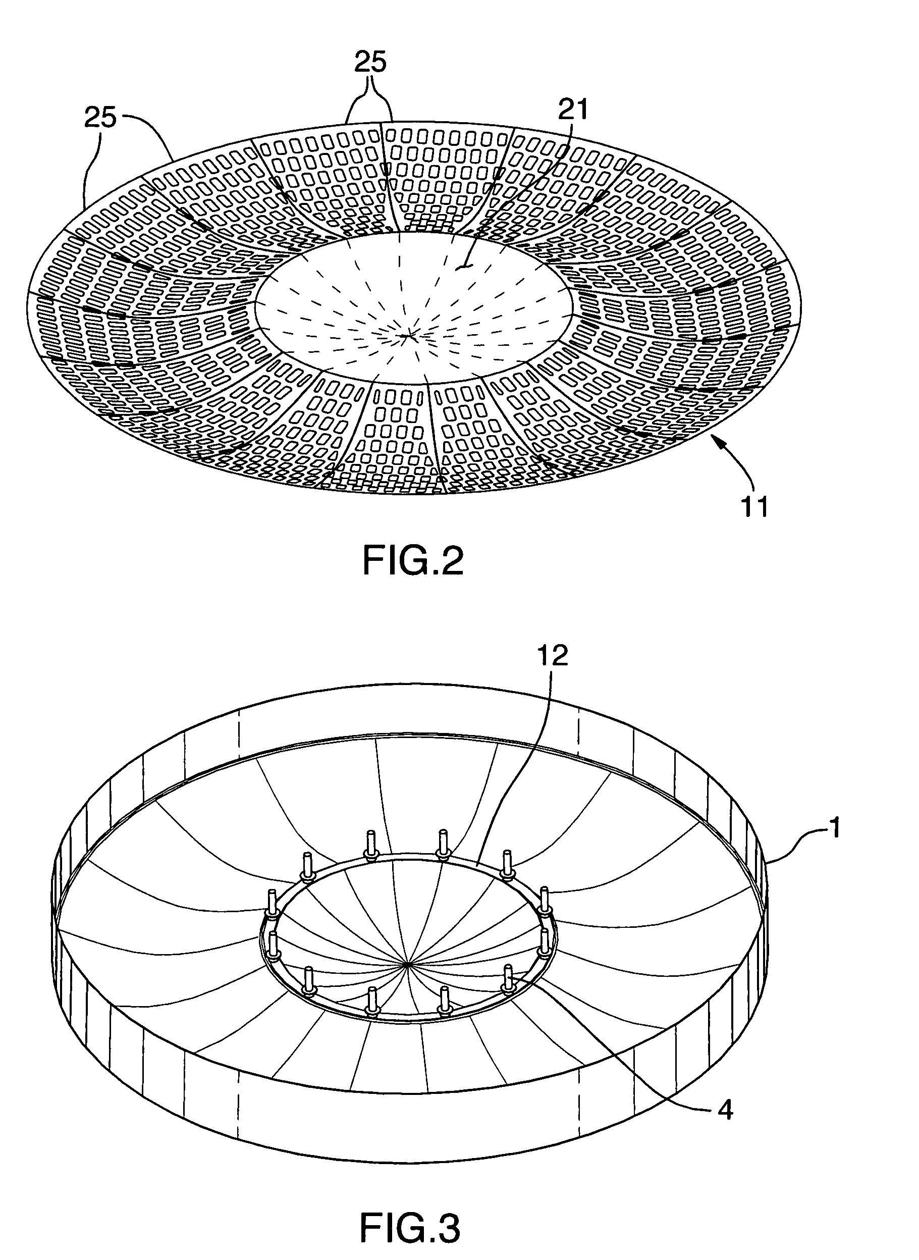
A converter having an exterior shell with a central axis, at least one gas inlet and at least one gas outlet. The exterior shell includes a base and an interior support structure. A number of vertically stacked catalytic chambers within the exterior shell are each in communication with one or more gas inlets and gas outlets. Each chamber is defined by an inner wall of the external shell, a permeable catalytic bed support platform, a lower division plate spaced below the platform defining a gas retention plenum and an upper division plate above the platform. At least one of: the platform; the upper division plate; and the lower division plate have a toroid surface symmetric about the central axis with an outer periphery supported by the inner wall of the exterior shell and an inner periphery supported by the interior support structure.

Description

TECHNICAL FIELD[0001]The invention relates to a gas converter for housing multiple beds of catalyst each on a tension stressed toroidal support platform with high temperature gas contained under pressure by a tension stressed toroidal division plate.BACKGROUND OF THE ART[0002]Industrial catalytic converters are used for example to convert sulphur dioxide gas to sulphur trioxide gas in the manufacture of sulphuric acid. Large pressure vessels of stainless steel have multiple layers of granular catalyst housed within the converters and gas is passed through the permeable granular catalyst beds under pressure and at elevated temperatures. Due to the highly corrosive nature of the gases, all ducting and support structures within the converter are constructed of stainless steel. Such structures are expensive to build due to the relatively high cost of materials, the complexity of welding stainless steel to maintain corrosion resistance, and the requirement of highly skilled labour often ...

Claims


Application Information

Patent Timeline
IPC IPC(8): B01J8/02B01J8/04
CPCB01J8/0242B01J19/248B01J19/249B01J2208/00194B01J2208/00814B01J2208/00884C01B17/803B01J2208/022B01J2219/2453B01J2219/2456B01J2219/2459B01J2219/246B01J2219/2481B01J2208/021
Inventor TABAK, ENRIQUE
Owner SNC-LAVALIN
Learn More