Abutment for a dental implant

a technology for dental implants and abutments, which is applied in the field of dental implants, can solve the problems of manufacturing the abutment, the limitation of the abutment to two base areas, and the complexity of the shape of the natural teeth

Active Publication Date: 2008-03-06
STRAUMANN HLDG AG
View PDF6 Cites 23 Cited by
  • Summary
  • Abstract
  • Description
  • Claims
  • Application Information

AI Technical Summary

Benefits of technology

[0006]Therefore, an object of the present invention is to provide an abutment for a dental implant which avoids the above-mentioned problems.
[0008]In addition, another object of the present invention is to provide an abutment for a dental implant which can be manufactured more easily, without the requirement for a shoulder of a regular width between an occlusal truncated cone of the abutment and the rim of the bases.

Problems solved by technology

In practice, however, it has been shown that this limitation to two base areas does not suffice for the complexity of shapes of the natural teeth.
In addition, EP-A-808 608 requires the provision of a shoulder of a regular width to be present between an occlusal truncated cone of the abutment and the rim of the differently shaped bases, which, with the small dimensions of the shoulder in the order of up to 0.1 mm, raises a problem in manufacturing the abutment.

Method used


Image

  • Abutment for a dental implant
  • Abutment for a dental implant
  • Abutment for a dental implant

Examples


first embodiment

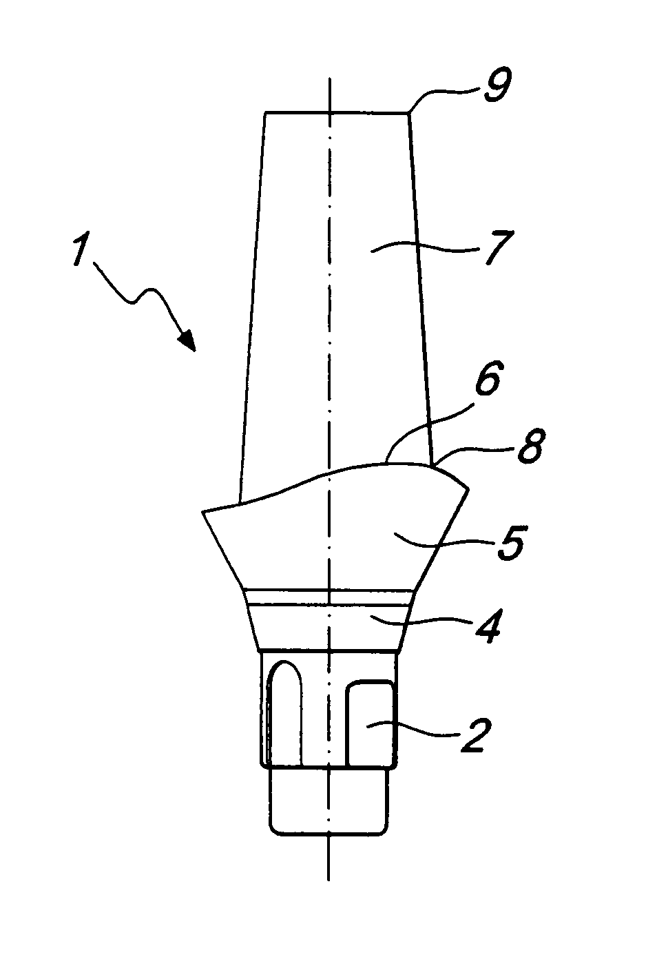
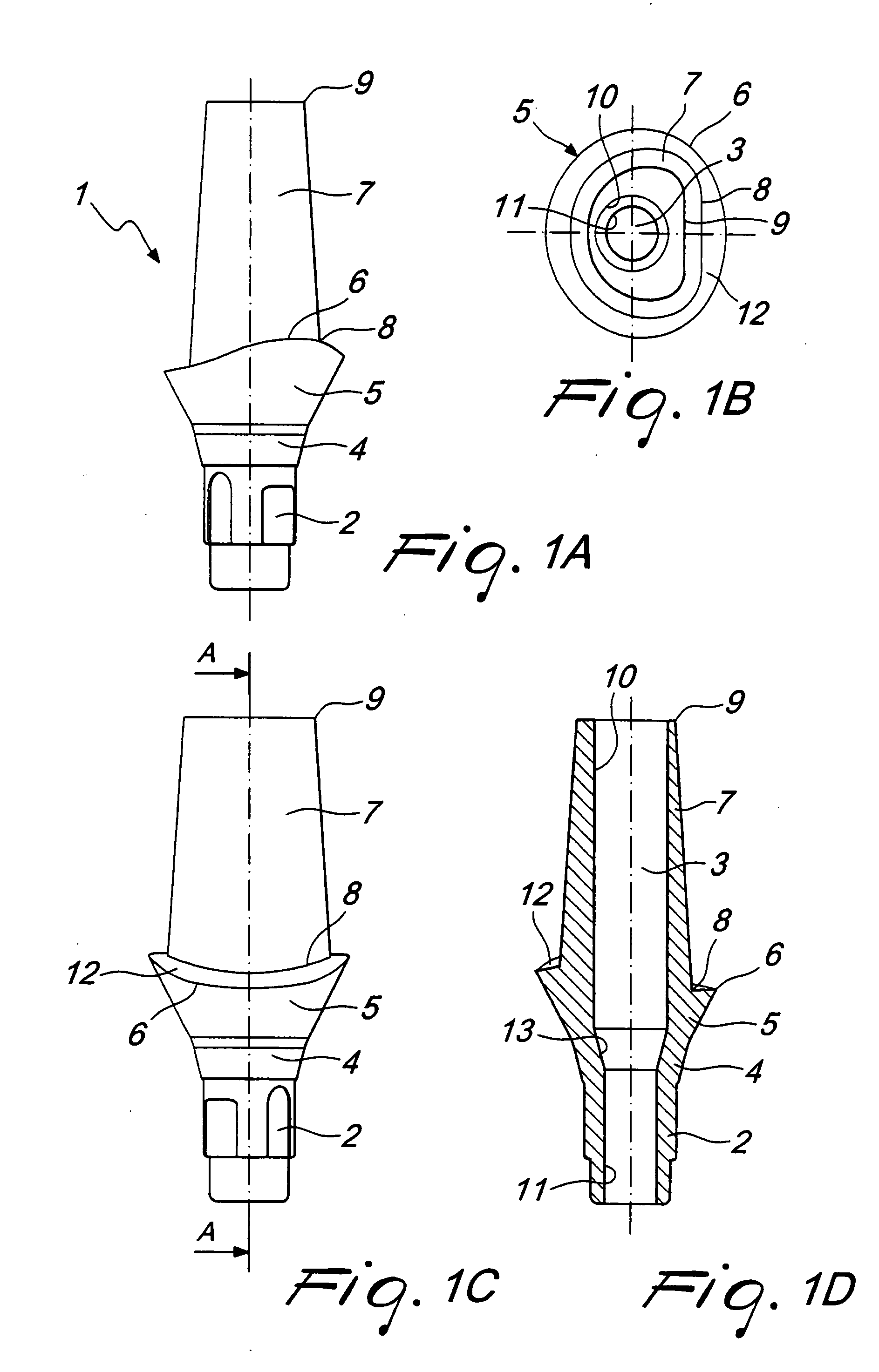
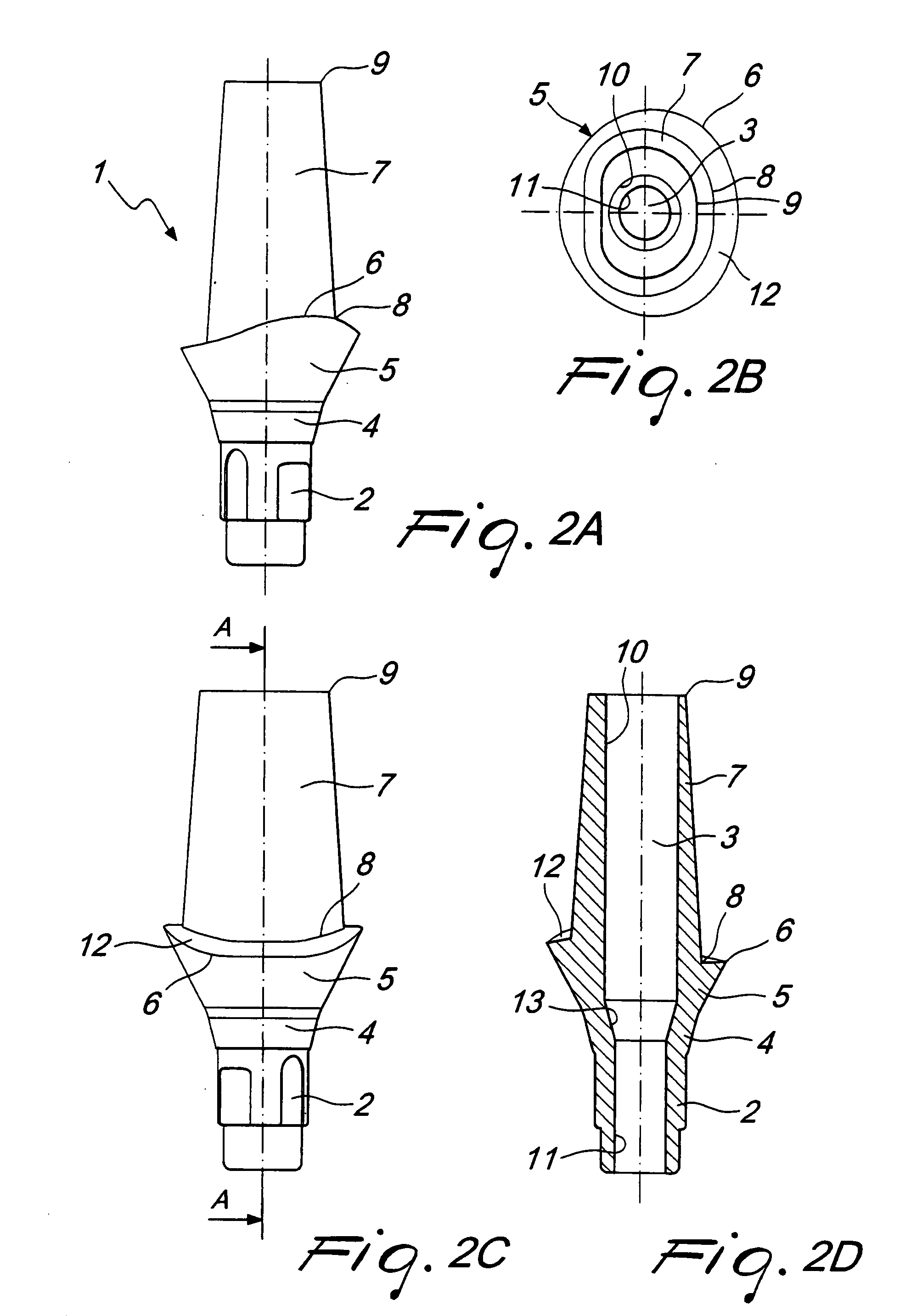
[0037]With reference to FIGS. 1A through 1D, the abutment for a dental implant according to the present invention is described. The abutment, generally identified by reference number 1, is provided with a base portion 2 adapted to be accommodated in an implant (not shown). As is well-known to the person skilled in the art, the base portion 2 has profiled sections for securing the abutment 1 against rotation in the implant. In addition, the abutment 1 is provided, as is well-known in the art, with a through bore 3 adapted to accommodate a screw (also not shown) for securing the abutment to the implant.

[0038]The base portion 2 of the abutment 1 borders on a rotationally symmetrical transition portion 4 which is preferably configured as a truncated cone.

[0039]The transition portion 4 goes over to a section 5 having in its approximal view a wave-shaped upper rim 6, with a crest in the approximal region and soles in the lingual and labial section, respectively. As can be seen in FIG. 1A,...

sixth embodiment

[0053]Differing from the previous embodiments, the occlusal portion 7′ is configured as a cylinder in the

[0054]In addition, the cross-section of the cylinder, as can be seen from the diagrams in FIGS. 6B and 6E (the through hole having been omitted for simplification), consists of a plurality of circular arcs 21′, 21″, 22′, 22″, 23′, 23″ and 24′; or 25′, 25″, 26′, 26″, 27′, 27″ and 28′, respectively, with different radii; each two circular arcs opposite to each other at the axis of symmetry 20 having identical radii.

[0055]In the sixth embodiment, the variation in width of the shoulder 12 amounts to about 45%.


PUM


Abstract

Abutment for a dental implant comprising: an apical base portion equipped with profiled sections, a rotationally symmetrical transition portion bordering coronally on the base portion, a section bordering coronally on the transition portion and equipped with a wave-shaped rim, and an occlusal portion bordering coronally on the transition portion, the occlusal portion not being configured circular symmetric, and an shoulder of irregular width being formed between the upper rim of section and the lower rim of the occlusal portion, the variation in width of the shoulder ranging between about 20% and about 300%.

Description

[0001]The present invention refers generally to an abutment for a dental implant and specifically to an abutment for a dental implant with an improved occlusal portion.BACKGROUND OF THE INVENTION[0002]From US-A-5 674 069, there is known an abutment adapted for patients and having an occlusal asymmetrical truncated cone.[0003]From EP-A-808 608, there is known an abutment for dental implants, an apical section of the abutment extending from the enossal portion of the dental implant being configured in the form of a symmetrical truncated cone bordering on a further coronal portion of the abutment which is configured asymmetrically; in particular, the latter portion of the abutment lingually has a parabolic base and labially a hemiellipsoidal base.[0004]This asymmetry in EP-A-808 608 is supposed to ensure, as far as possible, an adaptation to the shape of the natural teeth within the oral cavity. In practice, however, it has been shown that this limitation to two base areas does not suf...

Claims


Application Information

Patent Timeline
Patent Type & Authority Applications(United States)
IPC IPC(8): A61C8/00
CPCA61C8/005A61C8/0066A61C8/0054
Inventor ZETTLER, MARCSCHURCH, HANS
Owner STRAUMANN HLDG AG
Why Eureka
Try Eureka