Control of a defibrillator and/or pacemaker

a technology of defibrillator and pacemaker, which is applied in the field of control of defibrillator and/or pacemaker, can solve the problems of high rate of sudden death due to cardiac arrest, and the need for defibrillator shock to be administered within a very short tim

Active Publication Date: 2008-03-06
MATOS JEFFREY A
View PDF7 Cites 172 Cited by
  • Summary
  • Abstract
  • Description
  • Claims
  • Application Information

AI Technical Summary

Problems solved by technology

Cardiac arrest outside of the hospital is nearly always fatal.
Despite the fact that for decades, defibrillator technology—which has the potential to restore a survivable heart rhythm when a lethal one has caused the arrest—has been available, the rate of sudden death due to cardiac arrest remains very high.
The crux of the problem is that a defibrillator shock must be administered within a very short time after the onset of the arrest-causing heart rhythm—generally ventricular tachycardia (VT) or ventricular fibrillation (VF).
Drawbacks of AEDs include: 1) They may malfunction.
Some malfunctions are those that can occur with any electronic device, i.e. due to component failure.
Other malfunctions may be related to inadequate maintenance of the device by the owner.
Still other problems are due to “pseudo-malfunctions.” One type of pseudo-malfunction is that the algorithm for ECG analysis may fail to properly diagnose the rhythm abnormality.
There is no algorithm which is 100% accurate.
Thus an AED which fails to shock because it's algorithm is not 100% sensitive (i.e. does not correctly detect 100% of actual VT or VF) may be operating according to specification even at the time of a failure to make a correct diagnosis; If an identical rhythm were presented to another AED with the same algorithm, that AED would also fail to properly diagnose.
Another common type of pseudo-malfunction is the user failing to properly use the device.
Despite decades of effort by various workers to teach CPR to a broad fraction of the general population, most people do not know how to do it, and do not want to learn how.
3) A third AED drawback: For not-hard-to-understand reasons, most people are quite uncomfortable with the notion of presiding over a do-it-yourself cardiac arrest.
The anxiety results in limitation of sales and deployment of AEDs and in bystander reluctance to get involved.
Even experienced physicians and emergency workers are anxious during an actual arrest; As a result their performance suffers.
4) A fourth AED drawback: legal issues.
Although good Samaritan statutes provide protection for some situations, they are not uniform and do not protect the involved bystander or AED owner under all circumstances.
A difficult, if not impossible to measure parameter is ‘How many people do not obtain AEDs because of fear of a potentially burdensome legal entanglement?’
The hospitalization for the implant may cost as much as two or more times the device cost.
The total cost to the healthcare system for such devices is large.
As the medical indications for ICD implantation have broadened, and the number of implants has significantly increased, total costs to the health care system have gone up very substantially.
Although indications for some implants are uniformly agreed upon (e.g. cardiac arrest not due to a myocardial infarction in a young person with a depressed ejection fraction and no clear reversible cause), it has become clear that there is a gray-zone of people with intermediate levels of risk, for whom there is not uniform agreement about implantation.
Some highly respected authorities have raised serious concerns about excessive or potentially excessive numbers of ICD implants.
Although home AEDs are a possible alternative to ICDs in such gray-zone situations, there has been extraordinarily little enthusiasm for this approach, among physicians and patients.
2) Maintenance cost.
Though they seldom fail to shock for an actual VT or VF event, various lower level device malfunctions are not uncommon.
All U.S. manufacturers have reported component and software failures from time to time during recent years, some catastrophic, resulting in death.
Furthermore, pseudo-malfunctions, i.e. malfunctions due to improper programming are possible and certainly do happen.
Inappropriate shocks can be a big problem because
the shock, though brief, is painful, and generally heightens the patient's anxiety level for quite some time beyond the actual event.
One of the most notorious ICD failures, which resulted in loss of life, was ultimately patched by a software fix.

Method used


Image

  • Control of a defibrillator and/or pacemaker
  • Control of a defibrillator and/or pacemaker
  • Control of a defibrillator and/or pacemaker

Examples


Embodiment Construction

[0075] In the disclosure hereinabove and hereinbelow: [0076]“Defibrillation” and “defibrillator” are the nouns used to refer to the act of and the device which terminates a rapid heart rhythm with a non-synchronized shock. These two terms are, herein, intended to also refer to “cardioversion” and “cardioverter”, respectively, these latter two terms implying a synchronized shock.

[0077] The detailed description may be broadly divided into: [0078] 1) Overview of device function (FIGS. 1-5) [0079] 2) Example: System with unified adapter and communication device (FIGS. 6-9) [0080] 3) Example: Detailed Description of a modified external defibrillator system which may have various embodiments (FIG. 10) [0081] 4) Example: System with unified adapter and cardiac monitoring and treatment device (FIGS. 11-13) [0082] 5) Example: Versions of the system with at least one implantable component (FIGS. 14A, 14B and 14C).

Overview of Device Function

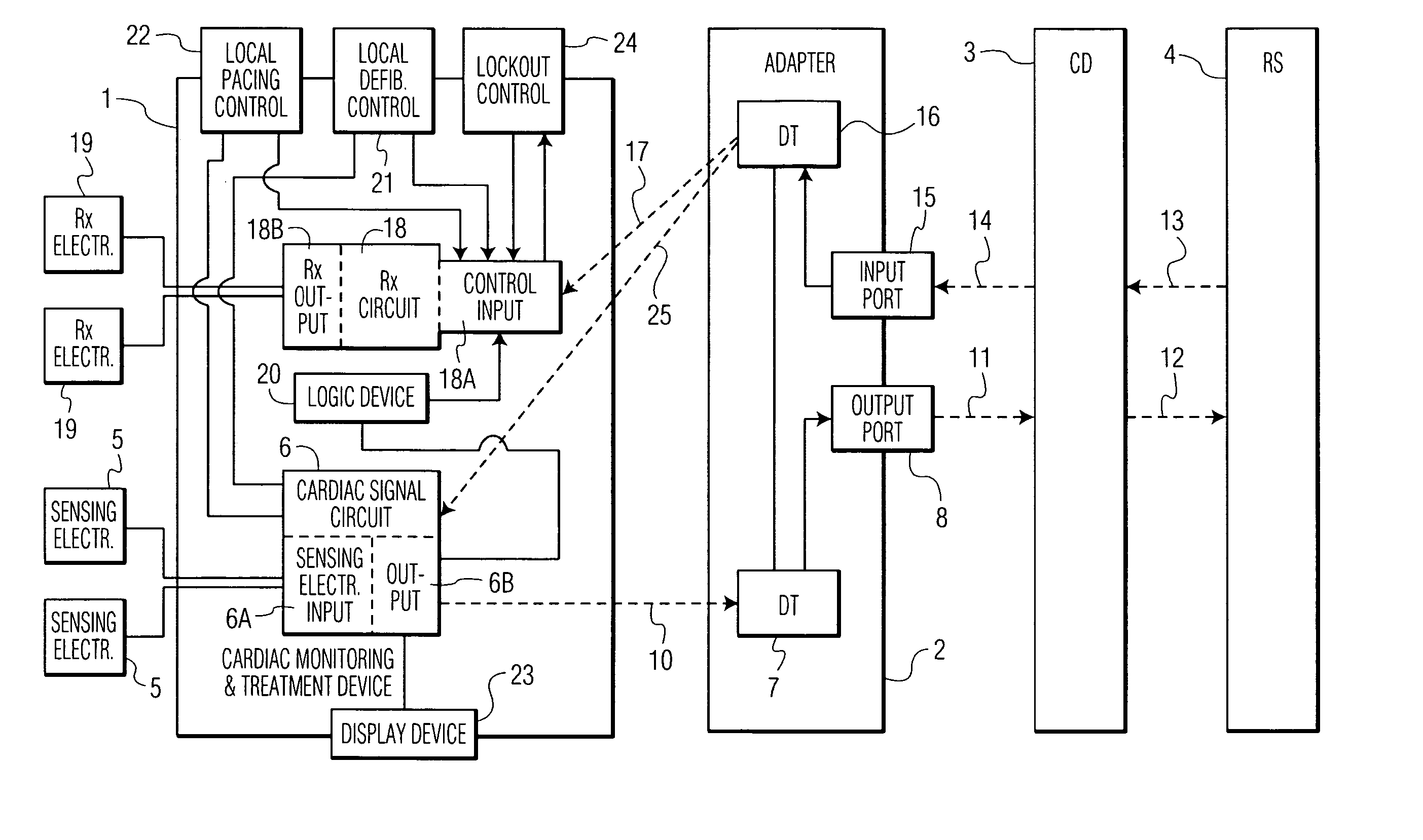
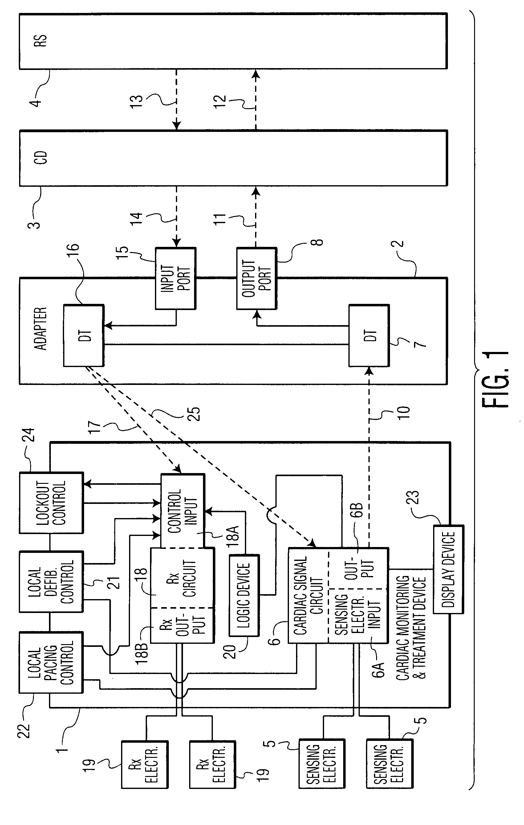
[0083]FIG. 1 shows an overview of a generalized v...


PUM


Abstract

A cardiac monitoring and treatment apparatus allows a victim of a medical emergency access to a medical professional (MP) who can monitor, diagnose and treat the victim from a remote site. The apparatus includes a cardiac monitoring and treatment device (CMTD) coupled to an electronic adaptor designed to communicate with a local, first transmitting/receiving (T/R) device which, in turn, is adapted to electronically communicate with a remote, second transmitting/receiving (T/R) device used by the MP. The CMPD comprises a cardiac treatment circuit for effecting cardiac pacing and/or defibrillation and a cardiac signal circuit for receiving cardiac signals. The cardiac signals are (1) transmitted from the signal circuit to the second T/R device for evaluation by the MP, (2) the MP may transmit a control signal to the treatment circuit, and (3), in response thereto, the treatment circuit may generate one or more electrical pulses for treatment of the victim.

Description

CROSS-REFERENCE TO RELATED APPLICATIONS [0001] The subject matter of this application is a related to that of the following applications: [0002] 1) U.S. patent application Ser. No. 10 / 460,458, published on Dec. 18, 2003 as U.S. Patent Publication No. US / 2003 / 0233129; and [0003] 2) U.S. patent application Ser. No. 11 / 502,484, published on Feb. 2, 2007 as U.S. Patent Publication No. US / 2007 / 0043585A1. [0004] This application also claims priority from the following provisional applications: [0005] 1) U.S. Provisional Application Ser. No. 60 / 840,722, filed Aug. 29, 2006; [0006] 2.) U.S. Provisional Application Ser. No. 60 / 928,567 filed May 10, 2007; and [0007] 3) U.S. Provisional Application Ser. No. 60 / 930,525 filed May 17, 2007. [0008] The aforementioned publications and applications are incorporated herein by reference.BACKGROUND OF THE INVENTION [0009] Cardiac arrest outside of the hospital is nearly always fatal. Despite the fact that for decades, defibrillator technology—which has...

Claims


Application Information

Patent Timeline
Patent Type & Authority Applications(United States)
IPC IPC(8): A61N1/00G06Q10/00G16H40/67
CPCA61N1/37282G06F19/3418A61N1/3962A61N1/39A61N1/3904A61N1/39622G16H40/67
Inventor MATOS, JEFFREY A.
Owner MATOS JEFFREY A
Why Eureka
Try Eureka