Turbine inverter

Inactive Publication Date: 2008-03-13
GLUZMAN ELI +2
View PDF9 Cites 25 Cited by
  • Summary
  • Abstract
  • Description
  • Claims
  • Application Information

AI Technical Summary

Benefits of technology

[0016]It is another objective of the present invention to provide a method of using the dev

Problems solved by technology

As the speed or pressure of fluid flow in pipes or hoses increases, as is inevitable during operation of almost all of the presently used machines and devices, laminar flow becomes increasingly more turbulent.
Drag due to boundary layer skin friction increases and turbulence causes the formation of eddies.
Because these machines and devices elicit turbulent fluid flow, they all suffer from an inherent inefficiency stemming from the need for additional energy to overcome these flow restrictions.
All of the

Method used


Image

  • Turbine inverter
  • Turbine inverter
  • Turbine inverter

Examples


Embodiment Construction

[0035]In the following description of the preferred embodiments, reference is made to the accompanying drawings which show by way of illustration specific embodiments in which the invention may be practiced. It is to be understood that other embodiments may be utilized and structural and functional changes may be made without departing from the scope of the present invention.

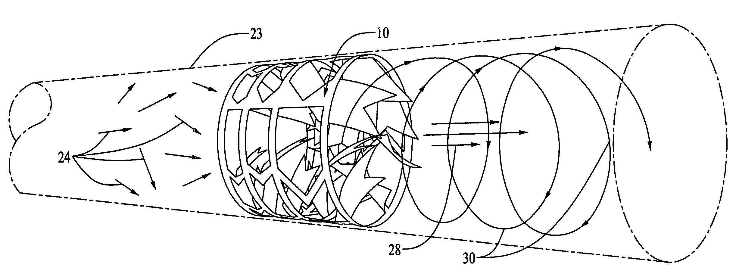
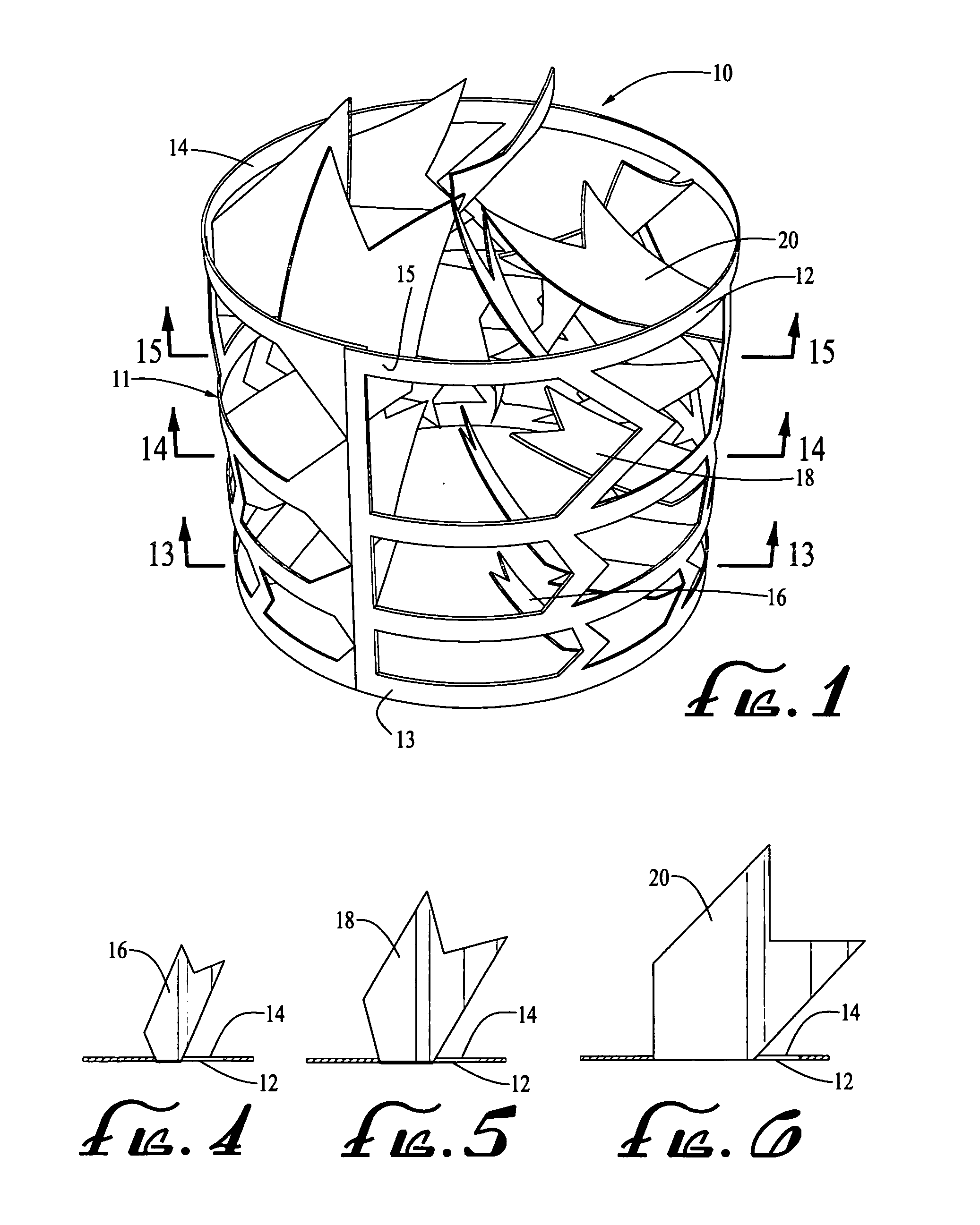
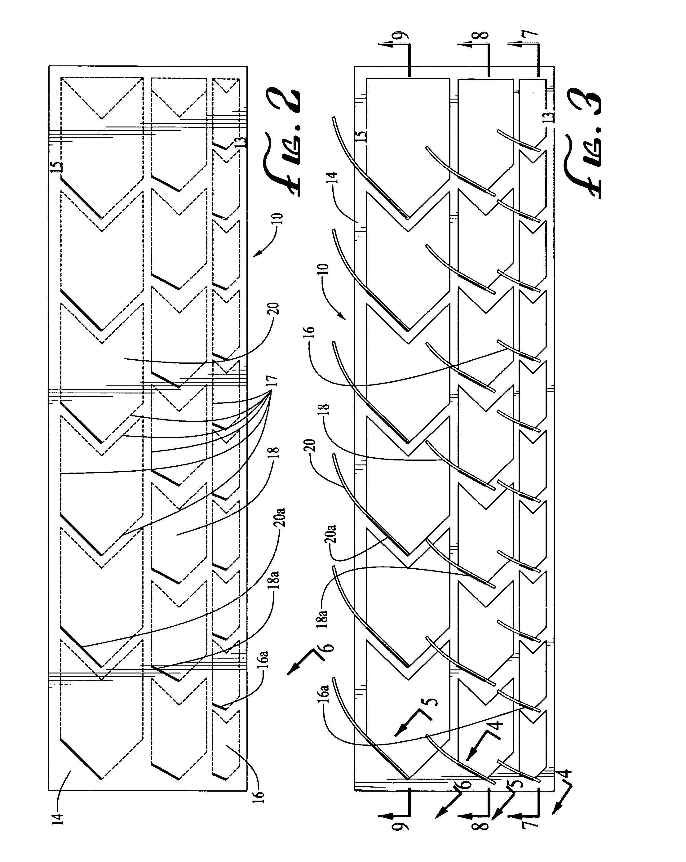
[0036]The present invention is a turbine inverter for improving the flow of fluids through any enclosed medium. FIG. 1 illustrates a preferred embodiment of the turbine inverter 10 of the present invention. The turbine inverter 10 has a main body 11. Although the main body 11 is preferably cylindrical, it could be of any suitable shape to complement the shape of the enclosed medium in which the turbine inverter is to be used. An example of such an enclosed medium could be a pipe, a hose, or a similar device typically used to transport fluids.

[0037]Referring to FIG. 1, the main body 11 is hollow and has an exteri...


PUM


Abstract

Disclosed is a fluid flow diverting device comprising a hollow main body and a plurality of blades protruding into the interior of the main body. The blades are positioned along the interior surface of the main body in multiple layers. The blades of each successive layer have a larger surface area and a larger entry angle of approach than the blades of a previous layer. The fluid diverting device can be inserted into any enclosed medium where fluids typically flow. The arrangement of blades diverts the flow of fluid in a way that creates a low pressure flow in the center of the enclosed medium. This low pressure flow is surrounded by high pressure flow, resulting in an increase in the swirling of matter and a pull of matter toward the center of the medium.

Description

FIELD OF THE INVENTION[0001]This invention relates generally to devices for improving the flow of matter (e.g., a gas or liquid) through an enclosed medium (e.g., a tube or duct of variable shapes) by diversion and redirection downstream from the devices, and more particularly, to devices for insertion into tube-like pathways in order to improve fluid flow.BACKGROUND OF THE INVENTION[0002]In fluid dynamics, turbulence is a flow regime characterized by chaotic property changes. Flow that is not turbulent is called laminar flow. When a fluid, i.e., liquid or a gas, flows through an enclosed medium with a relatively smooth interior surface, i.e., a pipe or a hose, the flow is typically laminar at very low speeds or low pressure. As the speed or pressure of fluid flow in pipes or hoses increases, as is inevitable during operation of almost all of the presently used machines and devices, laminar flow becomes increasingly more turbulent. In turbulent flow, unsteady vortices appear on many...

Claims


Application Information

Patent Timeline
IPC IPC(8): F15D1/04
CPCB01F5/0617B01F2005/0639F15D1/02F15D1/0015F15D1/0005B01F25/43151B01F25/431974
Inventor GLUZMAN, ELIGLUZMAN, STEFANYGLUZMAN, VADIM
Owner GLUZMAN ELI
Why Eureka
Try Eureka