
Marking instruments and methods of manufacturing marking instruments

a technology of marking instruments and marking pens, which is applied in the direction of writing connectors, propelling pencils, nibs, etc., can solve the problems of increasing the potential for fatigue and “writer's cramp”, the difficulty of keeping a writing and marking instrument in non-rigid small spaces, and the danger of the user, especially children, so as to increase the potential for fatigue and “writer's cramp” and be convenient and safe to carry on one's person, and convenient continuous use.

Inactive Publication Date: 2008-03-13
STEINSCHADEN ANDRE R
View PDF3 Cites 8 Cited by
  • Summary
  • Abstract
  • Description
  • Claims
  • Application Information

AI Technical Summary

Benefits of technology

[0008] The conventional rigid cylinder writing and marking instrument form has several disadvantages. The typical length, volume and rigidity of a writing and marking instrument make it difficult for a writing and marking instrument to be stored in non-rigid small spaces, such as a wallet, or a pocket which is part of the user's clothing. This limits the number of places that a writing and marking instrument can be comfortably and safely carried on one's person, and thus be conveniently continuously available for use. The generally narrow rigid cylindrical form offers only a limited contact surface for the user's hand, increasing the potential for fatigue and “writer's cramp” with prolonged continuous use. The rigidity results in the writing and marking instrument presenting a potential danger to the user, especially children, who can be accidentally poked and injured by the writing and marking instrument during its use, or while playing. The conventional form substantially limits the space available for decorating the writing and marking instrument and for applying information and advertisements.
[0009] There is therefore a need for a widely applicable writing and marking instrument which has either a semi-rigid or rigid form that can be more easily and safely stowed on one's person and is thus more conveniently available for use at any time. Accordingly, certain inventive embodiments described herein provide for a writing and marking instrument, as well as a writing and marking instrument which substantially increases the space available for decoration and for the affixing of information and advertisements, and which due to its form, facilitates the application of such decoration, information and advertisements.
[0010] Certain embodiments described herein increase the utility of common card-like devices by making it possible to integrate a convenient writing and marking instrument into both financial transaction card-like devices and non-financial transaction card-like devices, such as credit cards, microchip-containing smart cards, cards containing magnetic data storage devices, automatic teller machine (ATM) access cards, radio frequency (“RF”) and non-radio frequency access / security cards and entrance tickets, telephone access and stored value cards, stored value gift cards containing monetary value which can be redeemed at business establishments, customer and member “loyalty” cards such as distributed by retail businesses, travel-related businesses (airlines, hotels, auto rental, etc.), clubs, sports and entertainment establishments, wallet cards of photographic images, and similar card-like devices.
[0011] Further, certain embodiments utilize a card-like form for a writing and marking instrument, which uniquely offers increased contact surface area with the user's hand without requiring a large three-dimensional geometric volume. These embodiments distribute the muscle strain of holding the writing and marking instrument over a greater contact surface area, and decrease the potential for fatigue and “writer's cramp” with prolonged continuous use.
[0012] Certain embodiments further make it possible to integrate a writing and marking instrument into host devices, for example, key chains, clothing or hats, or common hand-held appliances, such as mobile telephones, electronic data devices, mini-computers, cameras, calculators, key chain transmitters, timekeeping devices including wristwatches, and similar devices, such that the writing and marking instrument is conveniently continuously available for use.

Problems solved by technology

The typical length, volume and rigidity of a writing and marking instrument make it difficult for a writing and marking instrument to be stored in non-rigid small spaces, such as a wallet, or a pocket which is part of the user's clothing.
The generally narrow rigid cylindrical form offers only a limited contact surface for the user's hand, increasing the potential for fatigue and “writer's cramp” with prolonged continuous use.
The rigidity results in the writing and marking instrument presenting a potential danger to the user, especially children, who can be accidentally poked and injured by the writing and marking instrument during its use, or while playing.
The conventional form substantially limits the space available for decorating the writing and marking instrument and for applying information and advertisements.

Method used


Image

  • Marking instruments and methods of manufacturing marking instruments
  • Marking instruments and methods of manufacturing marking instruments
  • Marking instruments and methods of manufacturing marking instruments

Examples


embodiment 76

[0086] Some or all of the edges of the body can be suitably rounded to provide a more ergonomic shape and feel which increases user comfort during marking. FIG. 6 shows an enlarged side edge perspective view of a card corner containing a marking device 2 with both straight edges 12, which are leading away from the corner arc of the body, being of a rounded form. The body edges can be rounded in the injection molding manufacturing method by using a molding die that has rounded edges in the molding cavity. In the lamination manufacturing method the body edges can be rounded by using a suitable forming die with rounded edges, or by milling the edges round. Alternatively, a rounded edge can be formed by adding a suitable rounded material, such as a convex molding, to the edges of the body. This rounded material can be attached to the body using various methods, such as laminating using heat, adhesives such as commercially available epoxies and glues, coatings, lasers, or other suitable ...

embodiment 38

[0103] Alternatively, the marking substance-containing apparatus can be in the form of a reservoir-like chamber which is tube-like and resembles a refill. Such a tube-like chamber can be made of a suitable material, such as an extruded plastic, and can be attached to the marking device, such that it is in fluid communication with it. Such a tube-like chamber can also contain an ink follower made of a suitable material, which ensures flow of the marking substance to the marking device. FIG. 12 shows an embodiment of a marking instrument containing a marking device 2a attached to a tube-like marking substance-containing apparatus 4a which is partially filled with a marking substance 5. FIG. 12 also shows a venting apparatus 3. FIG. 29 shows a coin-like embodiment 38 containing the same elements as FIG. 12.

[0104] Alternatively, the marking substance-containing apparatus can be in the form of a reservoir-like chamber which is bag-like and contains the marking substance in a sealed manne...


PUM


Abstract

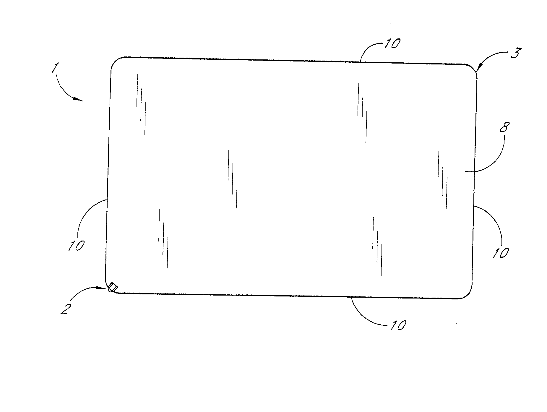
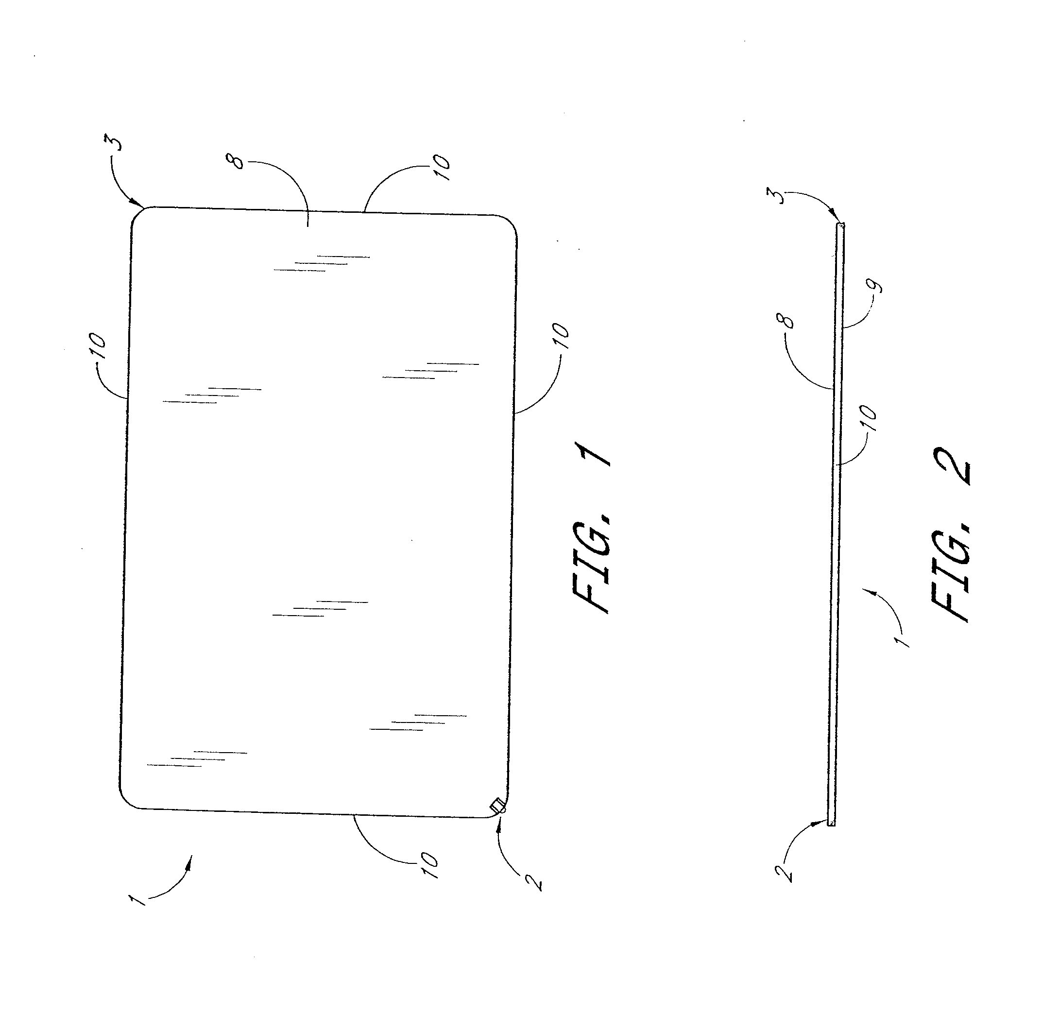
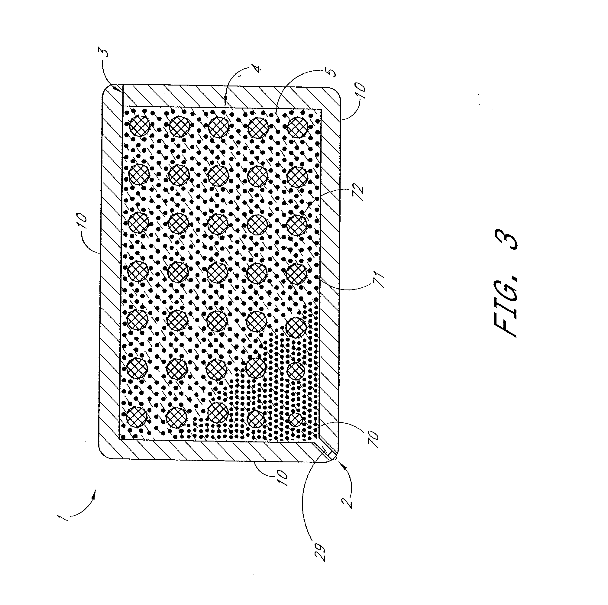
A handheld marking instrument includes a body having a substantially flat shape, a first chamber formed within the body and having an inner surface configured to receive and contain a marking substance within the body, and a first marking device configured to deliver the marking substance to a desired surface during marking. The first marking device is incorporated in the body and in communication with the first chamber to access the marking substance contained by the inner surface. At least a part of the first marking device is moveable between an exposed position for marking on the desired surface, and a retracted position. In one embodiment, the body has a form factor of a financial transaction card.

Description

PRIORITY APPLICATION [0001] This application is a continuation of U.S. patent application Ser. No. 11 / 018,544, filed Dec. 21, 2004, which is a divisional of U.S. patent application Ser. No. 10 / 354,263, filed Jan. 29, 2003, which claims priority under 35 U.S.C. §119(e) from U.S. Provisional Application No. 60 / 353,001, filed Jan. 29, 2002, the entirety of which are incorporated by reference.BACKGROUND OF THE INVENTION [0002] 1. Field of the Invention [0003] The present invention relates to a marking instrument. [0004] 2. Description of the Related Art [0005] Marking instruments of all types, three-dimensional shapes, and sizes exist, and may be used for writing and marking on a desired surface. The most common form for a marking instrument is a rigid extended cylindrical shape of varying length and diameter, containing an apparatus to contain a marking substance and / or solid (hereinafter referred to as a “marking substance-containing apparatus”), and an apparatus to suitably deliver t...

Claims


Application Information

Patent Timeline
IPC IPC(8): B43K29/00
CPCB43K1/08B43K29/093B43K5/02B43K5/16B43K7/005B43K7/02B43K7/04B43K7/12B43K8/003B43K8/02B43K8/03B43K8/24B43K11/005B43K21/006B43K23/008B43K23/08B43K25/00B43K25/02B43K27/02B43K27/04B43K27/08B43K27/12B43K29/00B43K29/003B43K29/004B43K29/007B43K29/08B43K29/087B43K5/005
Inventor STEINSCHADEN, ANDRE R.
Owner STEINSCHADEN ANDRE R
Learn More