Exercise machine

a technology of elliptical trainers and pedal assemblies, which is applied in the field of elliptical trainers, can solve the problems of preventing or hindering the movement of pedal assemblies, and achieve the effect of avoiding slippage of transmission belts

Inactive Publication Date: 2008-03-13
SUPERWEIGH ENTERPRISE
View PDF9 Cites 22 Cited by
  • Summary
  • Abstract
  • Description
  • Claims
  • Application Information

AI Technical Summary

Benefits of technology

[0007]Therefore, the object of the present invention is to provide an exercise machine that eliminates slippage of a transmission belt thereof.

Problems solved by technology

Since no component is provided for tensing the lower segment, slippage of the second transmission belt 164 can easily occur such that transmission of power is disturbed, resulting in hindering or stopping of movement of the pedal assemblies 19.

Method used


Image

  • Exercise machine
  • Exercise machine
  • Exercise machine

Examples


Embodiment Construction

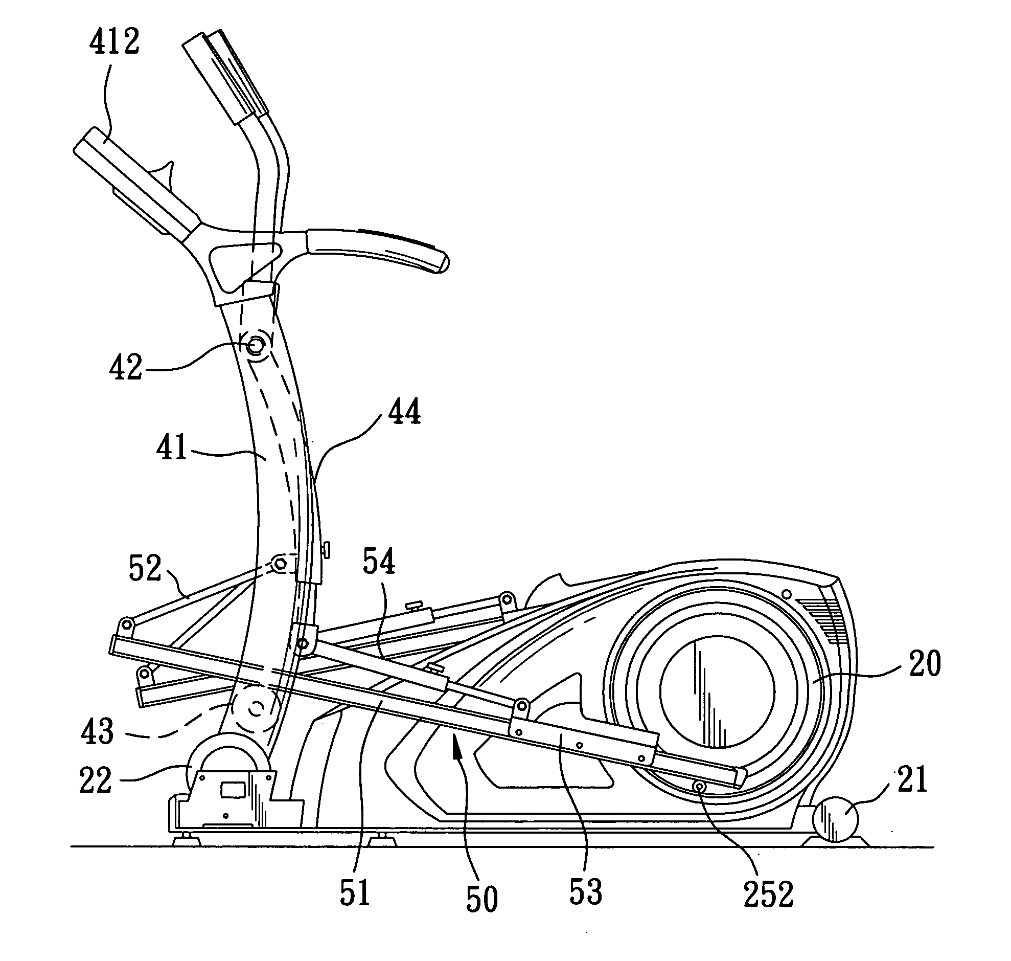
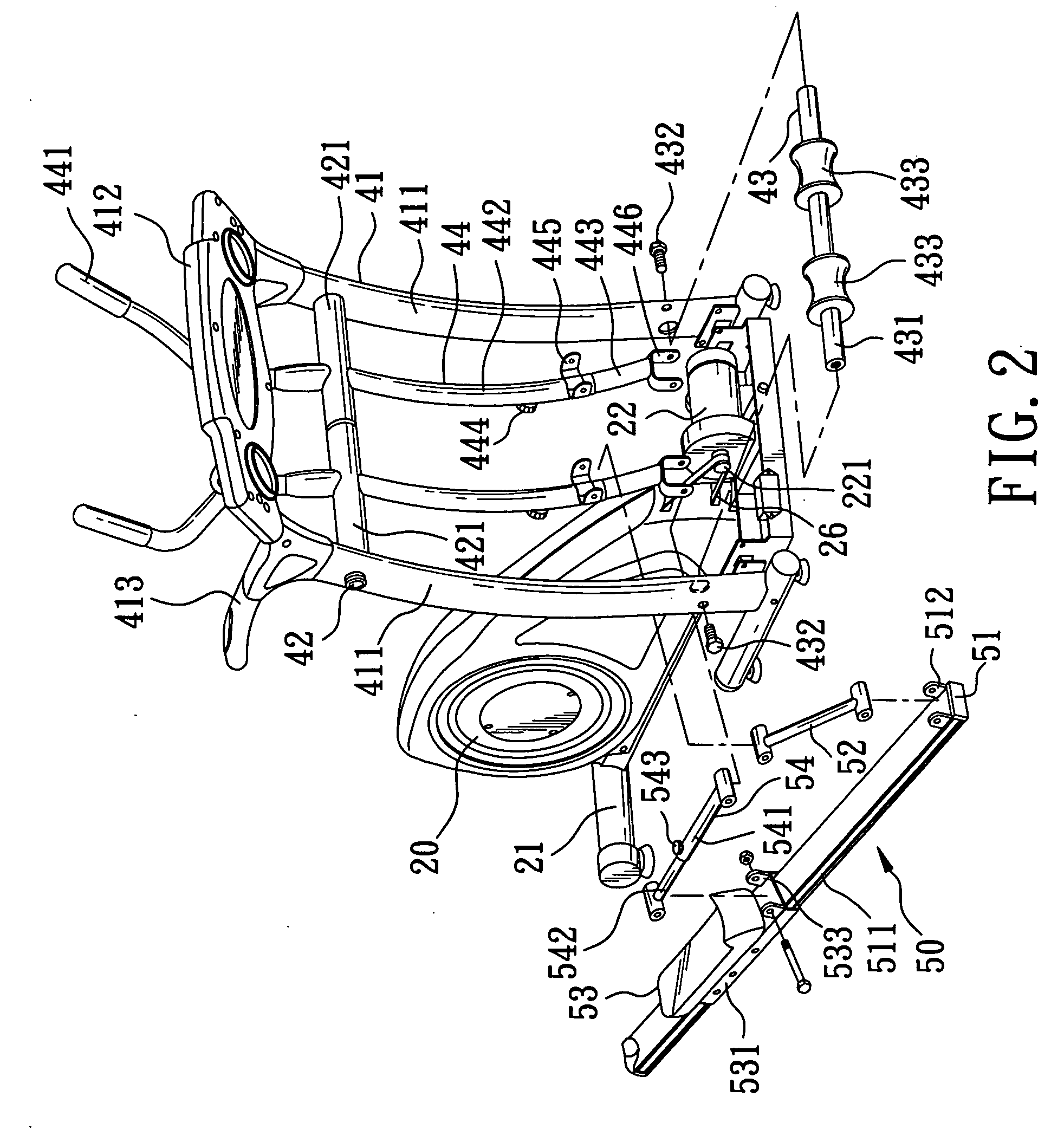
[0024]As shown in FIG. 2 and FIG. 3, the preferred embodiment of an exercise machine according to the present invention includes a base 21, an electric motor 22, a first support frame 23, a flywheel unit 24, a crank wheel unit 25, first and second transmission belts 26, 27, a pressurizing wheel mechanism 30, and two pedal assemblies 50 (only one is shown in FIG. 2). The first support frame 23, the flywheel unit 24, the crank wheel unit 25, the first and second transmission belts 26, 27, and the pressurizing wheel mechanism 30 are concealed in a housing 20.

[0025]As shown in FIG. 3 and FIG. 4, the electric motor 22 is mounted to a front end of the base 21. The first support frame 23 is mounted to the base 21 proximate to a rear end of the base 21. The fly wheel unit 24 is mounted rotatably to the first support frame 23, and is coupled to the electric motor 22 for assisting in rotation of the flywheel unit 24. The crank wheel unit 25 is mounted rotatably to the first support frame 23, ...


PUM


Abstract

An exercise machine includes: a flywheel mounted rotatably to a support frame; a crank wheel mounted rotatably to the support frame; a transmission belt trained on the flywheel and the crank wheel; and a pressurizing wheel mechanism including a mounting seat mounted to the support frame, upper and lower pressure wheel units provided pivotally on the mounting seat, and upper and lower limiting members mounted to the mounting seat. The upper and lower pressure wheel units respectively have upper and lower pressure wheels biased to move in first and second directions so as to press and tense upper and lower segments of the transmission belt that extend between the flywheel and the crank wheel. The upper and lower limiting members limit movement of the upper and lower pressure wheel units in directions opposite to the first and second directions, respectively.

Description

BACKGROUND OF THE INVENTION[0001]1. Field of the Invention[0002]The invention relates to an exercise machine, more particularly to an elliptical trainer.[0003]2. Description of the Related Art[0004]As shown in FIG. 1, a conventional elliptical trainer 10 includes a base 11, a first support frame 12 mounted proximate to and extending upwardly from a front end of the base 11, two swing handles 13 (only one is shown) mounted rotatably to the first support frame 12, an electric motor 14 mounted to the front end of the base 11, a second support frame 15 mounted to the base 11 proximate to a rear end of the base 11, a flywheel unit 16 mounted rotatably to the second support frame 15 and coupled to the electric motor 14 for assisting in rotation of the flywheel unit 16, a crank wheel unit 17 mounted rotatably to the second support frame 15 and disposed rearward of the flywheel unit 16, a pressure wheel unit 18 provided pivotally on the second support frame 15, and two pedal assemblies 19 (...

Claims


Application Information

Patent Timeline
Patent Type & Authority Applications(United States)
IPC IPC(8): A63B22/04A63B22/06
CPCA63B21/151A63B21/225A63B2225/30A63B22/0664A63B2022/067A63B22/001
Inventor LEE, SUNNY
Owner SUPERWEIGH ENTERPRISE
Why Eureka
Try Eureka