

Hydraulic lift rolling basket structure for a tillage implement
- Summary
- Abstract
- Description
- Claims
- Application Information
AI Technical Summary
Benefits of technology
Problems solved by technology
Method used
Image

Examples
Embodiment Construction
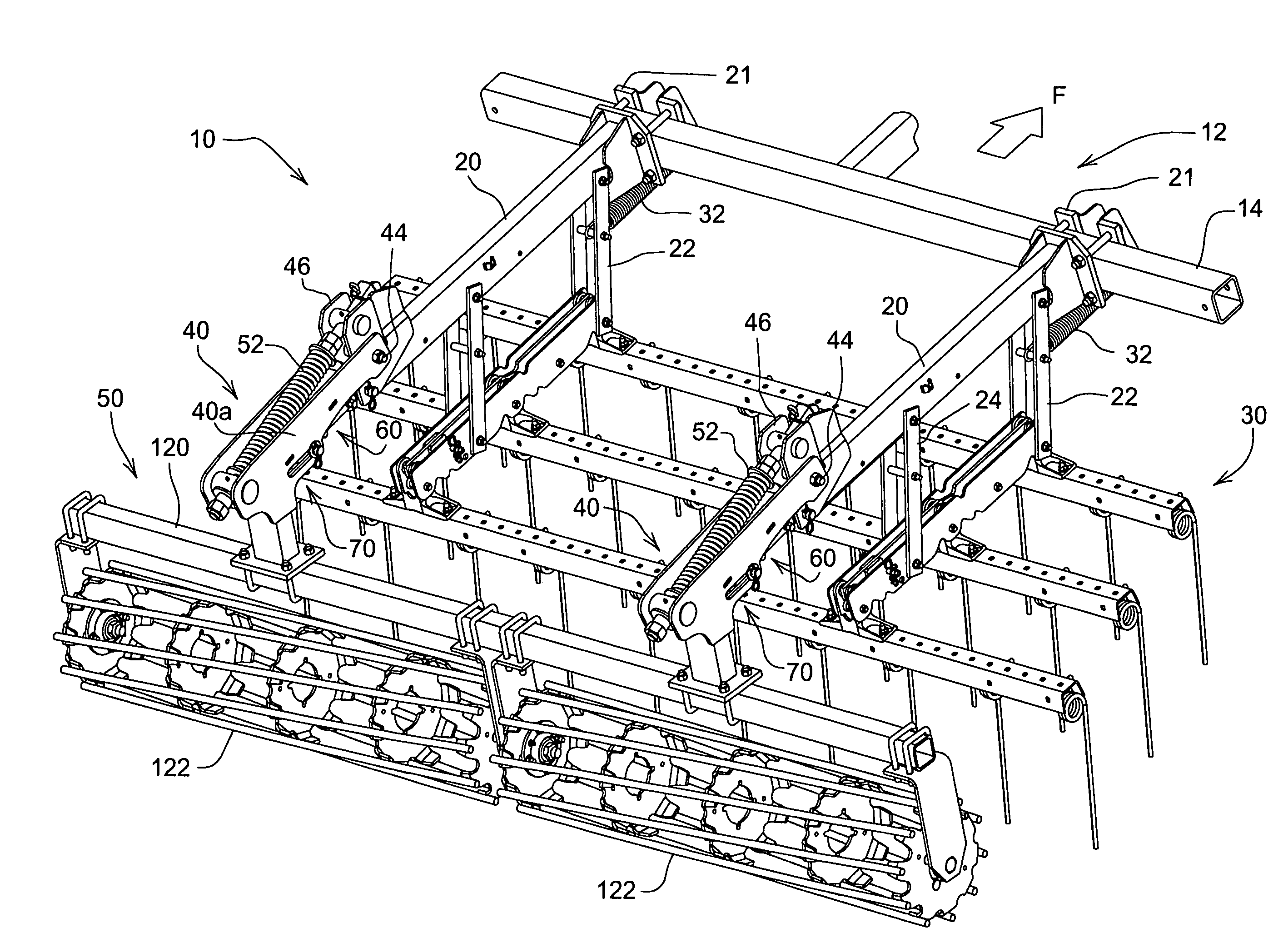
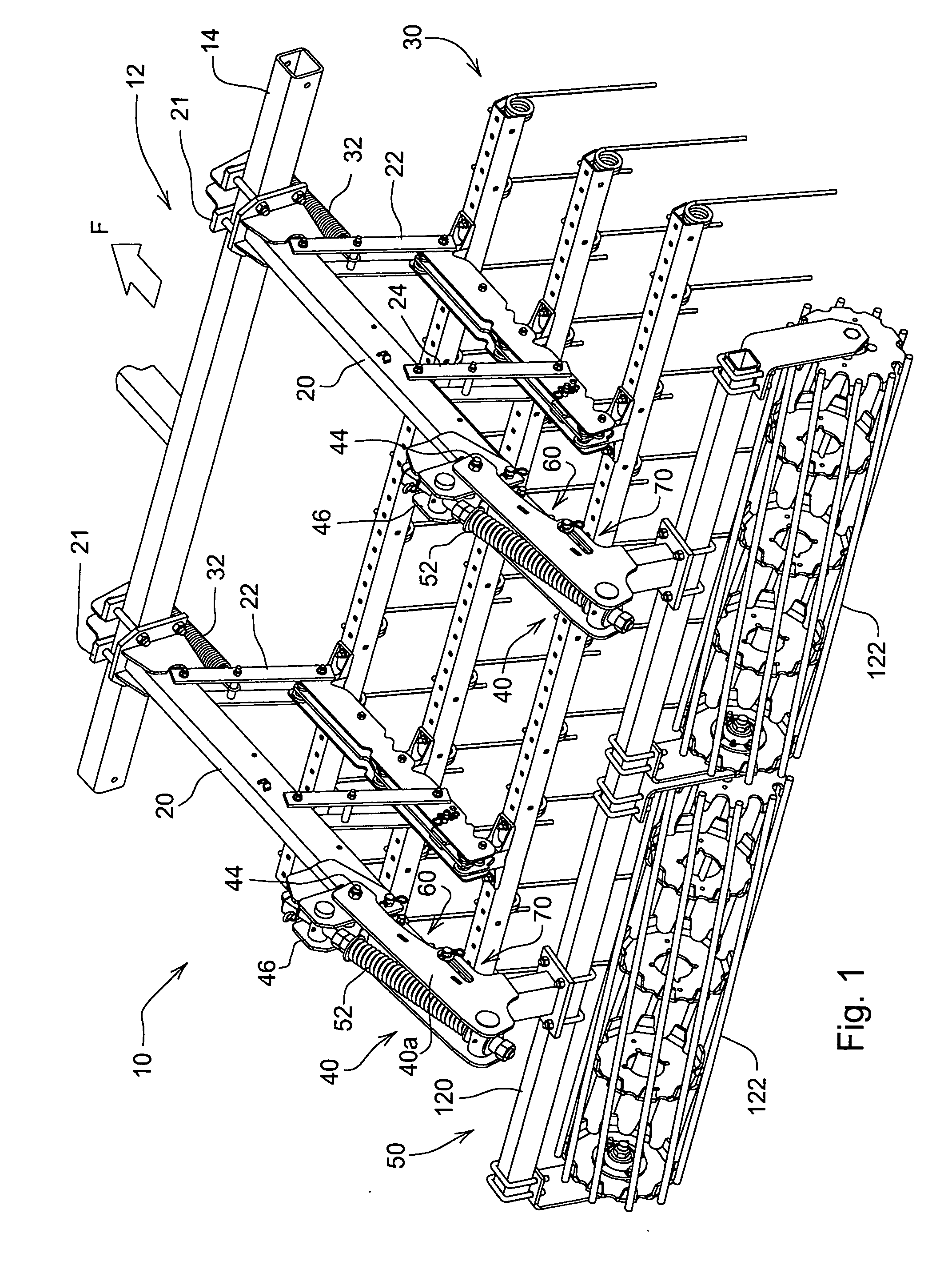
[0011]Referring to FIG. 1, therein is shown a portion of an agricultural tillage implement 10 having a fore-and-aft extending main frame 12 with a rear frame member 14. The main frame 12 supports conventional tillage tools (not shown) such as sweeps, shovels and / or disks for forward movement (F) through the soil.
[0012]Fore-and-aft extending support members 20 are transversely spaced on the rear frame member 14 by brackets 21 connected to forward ends of the members 20. As shown, the support members 20 extend in cantilever fashion generally horizontally in the plane of the main frame 12. Forward and aft links 22 and 24 are pivotally connected at upper ends to the support members 20. The links 22 and 24 depend from the members 20 and support a tine harrow 30 or similar tool for engaging the ground behind the rear frame member 14. Springs 32 connected between the brackets 21 and the links 22 help bias the harrow 30 downwardly and forwardly into ground contact. The harrow 30 includes co...
PUM
 Abstract
Description
Claims
Application Information