Vortex generator at hot gas output

a technology of hot gas and generators, applied in the direction of power plant exhaust arrangements, air-flow influencers, transportation and packaging, etc., can solve the problems of difficult identification, difficult prediction of complex aerodynamic and aerothermic phenomena, and difficult modeling of boundary layers, so as to achieve the effect of heavy aircraft structur

Active Publication Date: 2008-03-20
AIRBUS OPERATIONS (SAS)
View PDF7 Cites 36 Cited by
  • Summary
  • Abstract
  • Description
  • Claims
  • Application Information

AI Technical Summary

Benefits of technology

[0014]The invention proposes, among other advantages, to overcome the inconveniences of the existing solutions, by protecting the surface of the mast adjacent to the hot gases output of the engine without unduly making the structure of the aircraft heavier.

Problems solved by technology

Nevertheless, this identification is difficult because it must cover the entire flight domain of the plane.
In addition, it brings into play complex aerodynamic and aerothermic phenomena that are still difficult to predict; certain movements of hot air occur indeed exclusively within a “boundary layer”, i.e. over a very low thickness of turbulent flow between the surface of mast 2 and the cold exterior flow.
Boundary layers are particularly difficult to model.
These modifications result in an increase in the mass of the plane, which alone is already prejudicial, and in a penalty of aerodynamic drag if internal ventilation is increased.
This approach also bears heavy consequences in that it implies a modification in the manufacturing processes of the affected structures, and this late in the development of the plane.

Method used


Image

  • Vortex generator at hot gas output
  • Vortex generator at hot gas output
  • Vortex generator at hot gas output

Examples


Embodiment Construction

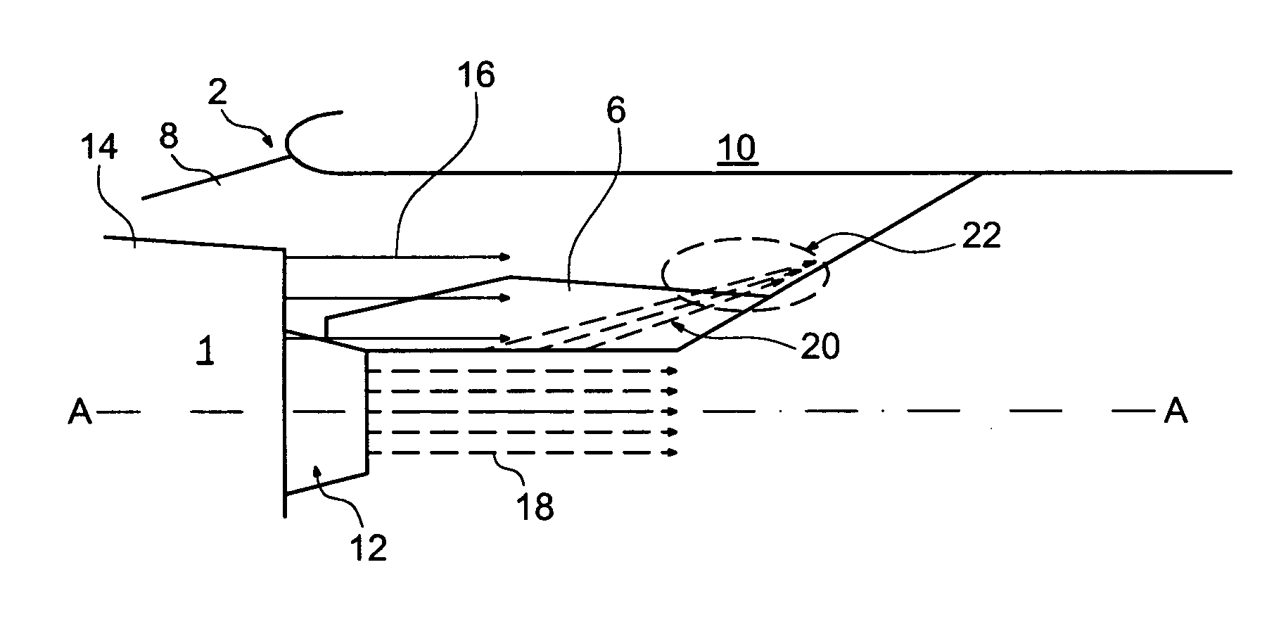
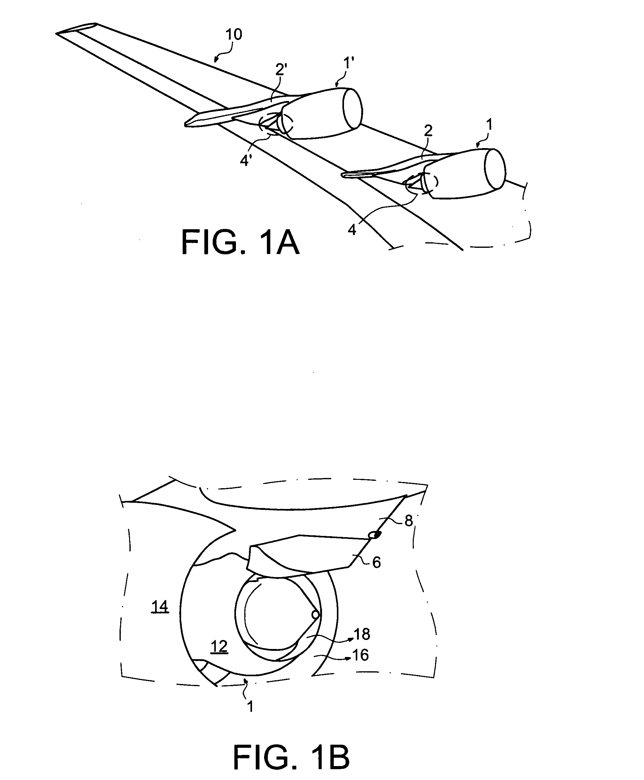
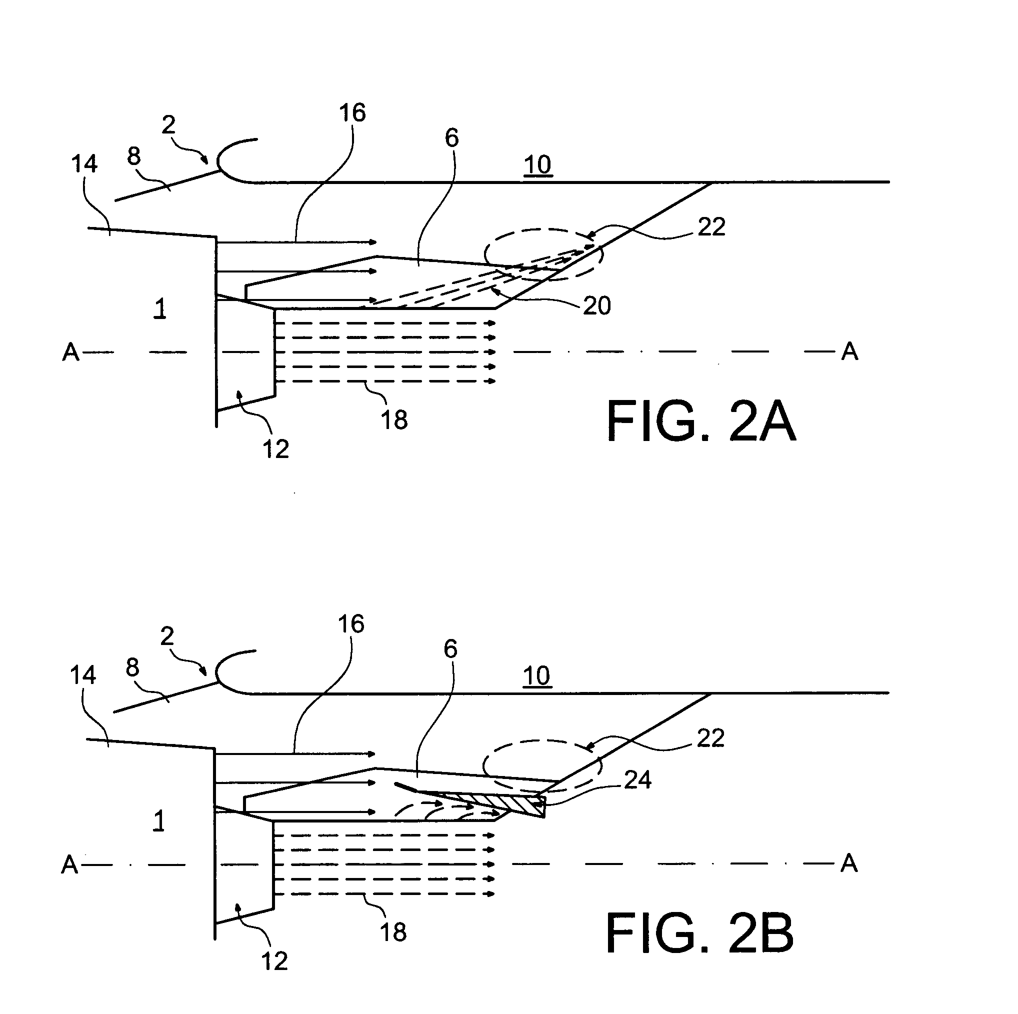
[0028]In aircraft, a usual design provides for an attachment mast in order to form the link interface between the engine such as a jet engine and an airfoil of the aircraft. This type of attachment mast, also called EMS (“Engine Mounting Structure”), makes it possible to suspend for example a jet engine below the airfoil of the aircraft, or to mount the jet engine above the airfoil, using several attachments; it makes it possible to transmit the efforts generated by its associated jet engine to the structure of the aircraft, and also allows for the carrying of fuel, air, electrical and hydraulic systems, etc. between the engine and the aircraft.

[0029]Therefore, as shown in FIGS. 1 and 2, an aircraft engine 1 is fixed under a wing 10 of the aircraft by an attachment mast 2. Jet engine 1 has in front a large-size fan casing that delimits a fan ring channel, and has towards the rear a central case that encloses the core of the jet engine 1; the central case extends towards the rear by ...


PUM


Abstract

In order to reduce the surface of a support mast (2) of an aircraft engine in contact with the hot exhaust gases (18) of said engine, a vortex-generating device (24) is positioned on the surface of the mast (2), near the hot region (22). Thus, the vortex generated in the flow of cold gases (16) crosses the hot air and modifies its path, thus preventing it from reaching zones (22) of the mast that are not predefined. This system makes it possible to adapt to the operating conditions of an already-built aircraft, without any notable increased weight.

Description

TECHNICAL DOMAIN[0001]The invention relates to the field of protection against overheating caused by hot exhaust gases from an engine by the creation of a flow that deviates said gases. The invention has a particular application in aeronautics, at the level of the surface of the structure that supports the engine, for example a mast.[0002]The invention thus relates to a method for protecting a structure located downstream from the directional evacuation of a hot gas by the implementation of a device that indirectly deviates this gas, in particular via a vortex. The invention also relates to a structural element equipped with such a vortex generator device.STATE OR PRIOR TECHNIQUE[0003]Although oriented in a direction fixed by an engine case, the hot exhaust gases come into contact with the adjacent parts at the output of the case. In particular, for an aircraft wherein engine 1, 1′ is mounted on a mast 2, 2′ (see for example document FR 2 807 389), the gases ejected by engine 1, 1′ ...

Claims


Application Information

Patent Timeline
Patent Type & Authority Applications(United States)
IPC IPC(8): B64C23/06
CPCB64C7/02B64C23/06B64D33/04Y02T50/162B64D29/02Y02T50/10
Inventor BONNAUD, CYRILHORMIERE, ARNAUD
Owner AIRBUS OPERATIONS (SAS)
Why Eureka
Try Eureka