
Frame interpolation apparatus and frame interpolation method

Inactive Publication Date: 2008-03-20
MITSUBISHI ELECTRIC CORP
View PDF5 Cites 13 Cited by
  • Summary
  • Abstract
  • Description
  • Claims
  • Application Information

AI Technical Summary

Benefits of technology

[0011]An object of the present invention is to provide a frame interpolation apparatus that can detect image motion accurately by a straightforward computational procedure with simple read and write address control.
[0017]Interpolation is straightforward because the same procedure is repeated at each interpolation position. Read and write address control is simplified for the same reason. The apparatus can be easily implements in hardware and the computations are amenable to parallel processing.

Problems solved by technology

A disadvantage of a hold-type display device such as a liquid crystal display (LCD), in which the same image is held on display for one frame period, is that although the human eye tracks the movement of a moving object in the image continuously, the object itself moves discontinuously, one frame at a time, causing the edges of the moving object appear blurred.
Film-to-video conversion of movies and the like causes another problem.
A similar problem occurs when a computer-processed moving image is converted to a video signal, because two video fields are created from the same computer-processed frame.
Zero-order hold interpolation cannot solve the blurring problem of a hold-type display, because it does not provide a smooth visual perception of an object moving in a fixed direction.
Mean value interpolation has the problem of producing double images or ‘ghosts’ of moving objects.
In this method, however, although the interpolated frame is built up a pixel block at a time, the interpolated pixel blocks usually do not fit together in uniform pattern.
Generating the necessary read and write addresses in the image data memory (SDRAM is used in general) and ensuing that interpolated pixels are obtained for all pixel positions becomes a complex process, making a hardware solution difficult.
Because correlation is based on individual pixels, however, high correlations between pixels in dissimilar parts of the image may arise by chance, producing false motion detection and an incorrect interpolated image.

Method used


Image

  • Frame interpolation apparatus and frame interpolation method
  • Frame interpolation apparatus and frame interpolation method
  • Frame interpolation apparatus and frame interpolation method

Examples


first embodiment

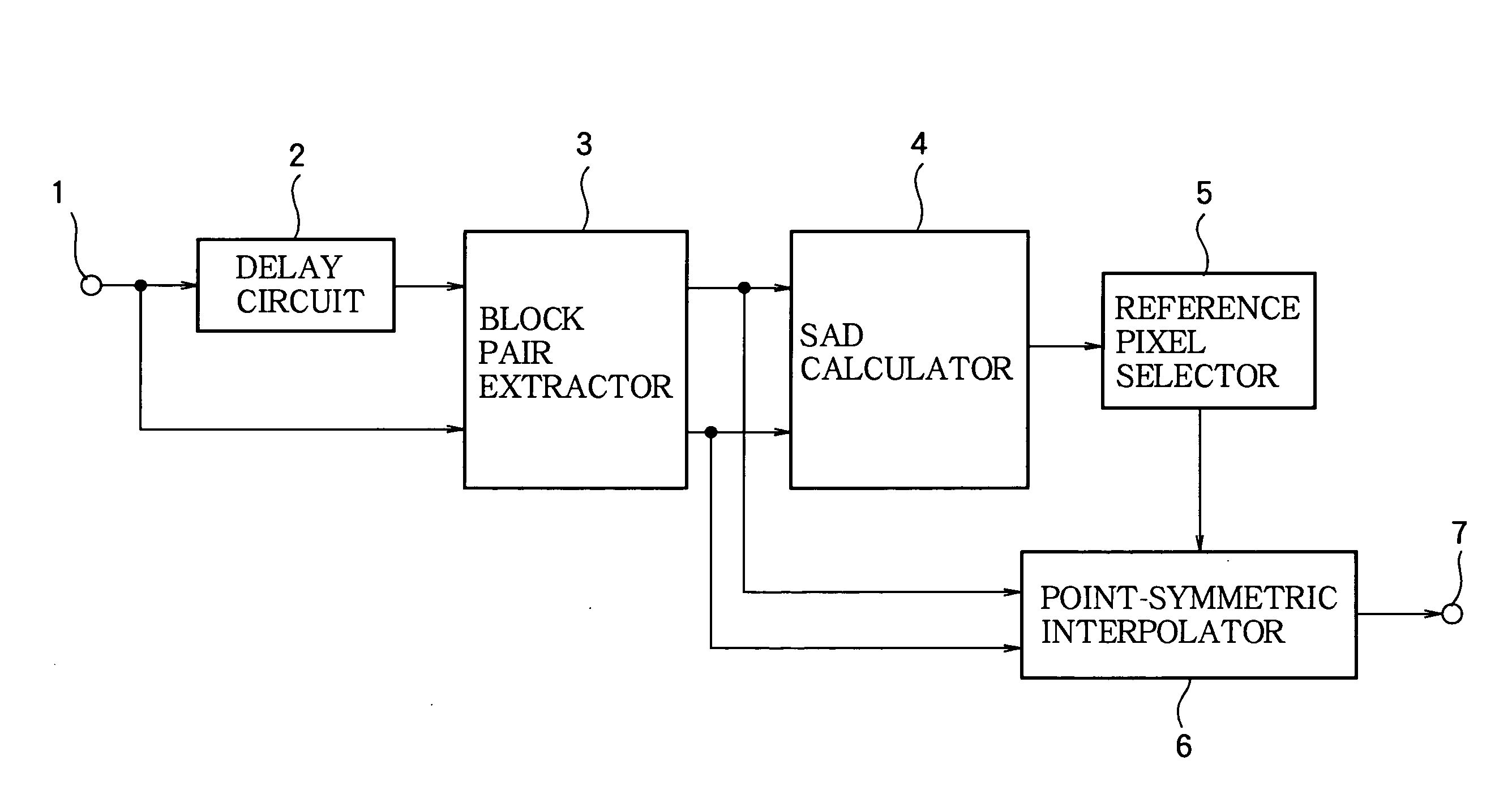
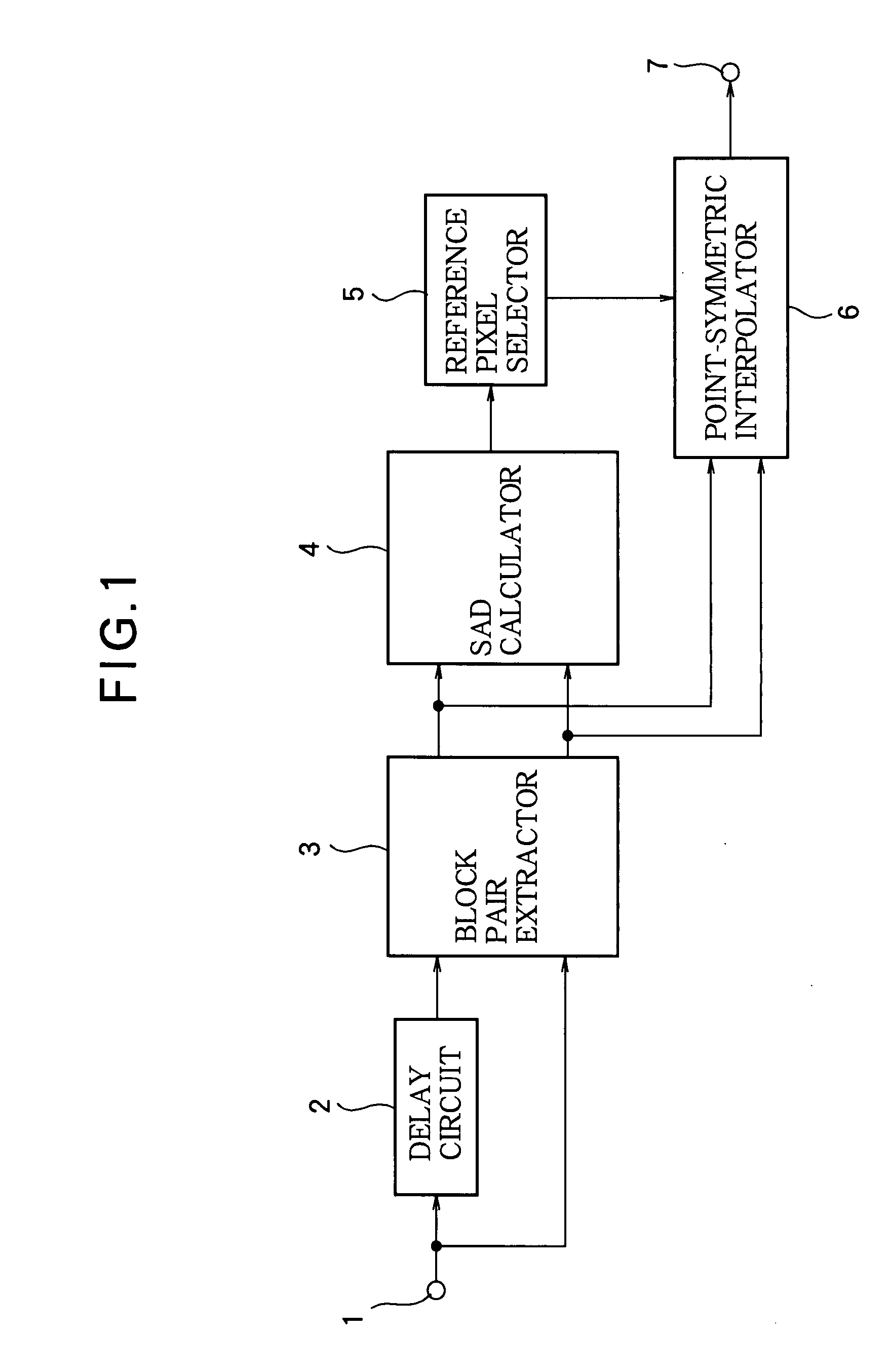
[0043]Referring to FIG. 1, the frame interpolation apparatus in the first embodiment comprises an input terminal 1, a delay circuit 2, a block pair extractor 3, a sum of absolute differences (SAD) calculator 4, a reference pixel selector 5, a point-symmetric interpolator 6, and an output terminal 7.

[0044]A video signal received at the input terminal 1 is input to the delay circuit 2, in which it is delayed by one frame period. The delayed video signal is input to one input terminal of the block pair extractor 3 as a first reference frame signal. The undelayed video signal is input to another input terminal of the block pair extractor 3 as a second reference frame signal. From the first and second reference frames, the block pair extractor 3 extracts pixel blocks that are point-symmetric or approximately point-symmetric as described below.

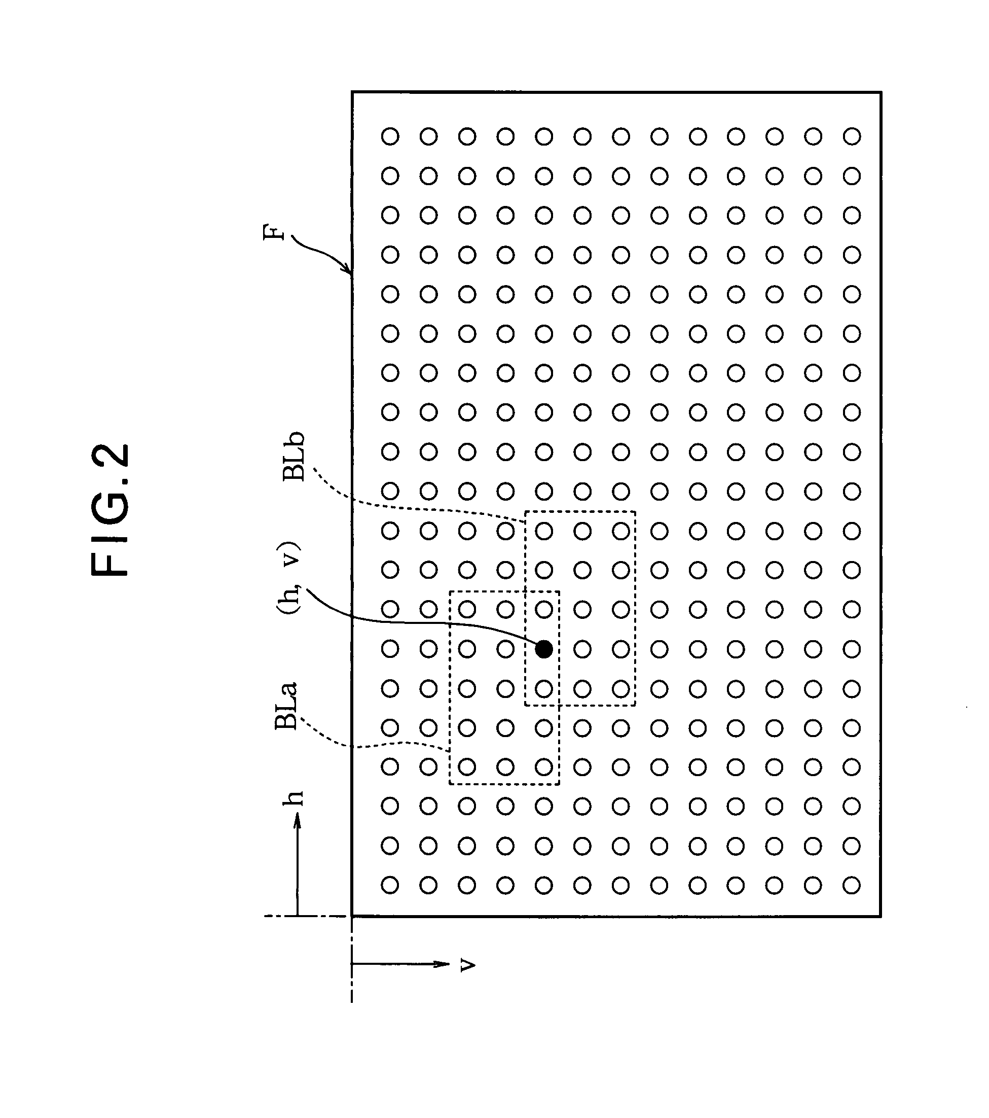
[0045]Referring to FIG. 2, the pixels in each frame F form a matrix on a display screen, consisting of rows aligned in the horizontal direction (th...

second embodiment

[0077]Although the first embodiment uses similarities calculated in the same way for all pairs of pixel blocks, there is a tendency for the reliability of the calculated similarity to decrease as the separation between the pixel blocks increases. The second embodiment corrects for this tendency by multiplying the calculated similarity values by coefficients that increase with increasing separation between the pixel blocks, so that pairs of mutually distant blocks are inherently considered to be less similar. The corrected similarity values are used as similarity indexes to select reference pixels.

[0078]Referring to FIG. 8, the structure of the frame interpolation apparatus is generally the same as in FIG. 1, but differs in that a similarity correction circuit 13 is added. The components having the same reference characters as in FIG. 1 perform the same operations as in FIG. 1.

[0079]The similarity correction circuit 13 corrects the similarity values by multiplying the sums of the abs...

third embodiment

[0088]Although the SAD calculator 4 in the first embodiment calculates similarities of pixel block pairs in the same way for both flat images (images with small pixel-to-pixel variations over a broad area of the screen) and non-flat images, there is a tendency for the calculated similarity to increase for flatter images, which can lead to inappropriate selection of reference pixels. The third embodiment corrects for this tendency by devaluating the similarities of pixel block pairs with flat image content, and uses the corrected values as similarity indexes, thereby improving the reliability of selection of the reference pixels.

[0089]Referring to FIG. 10, the structure of the frame interpolation apparatus is generally the same as in FIG. 1, but differs in that a correction control circuit 27 and a correction circuit 28 are added. The components having the same reference characters as in FIG. 1 perform operations similar to those in FIG. 1.

[0090]The similarity index generator 32 comp...


PUM


Abstract

A frame interpolation apparatus generates a pixel value at an interpolation position by examining pairs of pixel blocks, one from a preceding reference frame and one from a following reference frame, located in positions that are point-symmetric or nearly point-symmetric with respect to the interpolation position. The pair of pixel blocks showing the greatest mutual similarity is selected, the central pixels in the selected pair of pixel blocks are taken as reference pixels, and the interpolated pixel value is generated from the reference pixel values. By routinely examining a large number of pairs of pixel blocks for each interpolation position, the frame interpolation apparatus can detect image motion accurately and generate accurate interpolated values.

Description

BACKGROUND OF THE INVENTION[0001]1. Field of the Invention[0002]The present invention relates to a frame interpolation apparatus and a frame interpolation method for interpolating an image between two frames of a video signal.[0003]2. Description of the Related Art[0004]A disadvantage of a hold-type display device such as a liquid crystal display (LCD), in which the same image is held on display for one frame period, is that although the human eye tracks the movement of a moving object in the image continuously, the object itself moves discontinuously, one frame at a time, causing the edges of the moving object appear blurred. One possible solution to this problem is to perform frame interpolation to increase the frame rate, thereby producing a smooth visual perception of moving objects.[0005]Film-to-video conversion of movies and the like causes another problem. Because of the different frame rates of film and video, a single image frame taken from film is sometimes displayed in tw...

Claims


Application Information

Patent Timeline
IPC IPC(8): H04N7/26
CPCH04N7/0132G09G2340/0435H04N7/0145H04N7/0137
Inventor MINAMI, KOJIGAI, TOSHIHIROYASUI, HIRONOBUSOTODA, SHUJISAKUWA, CHIHIROFUJIWARA, TAKASHI
Owner MITSUBISHI ELECTRIC CORP
Learn More