
Determination and adjustment of laser modulation current in an optical transmitter

a technology of optical transmitter and laser module, which is applied in the direction of optical elements, instruments, transmission monitoring, etc., can solve the problems of transceiver design typically not enabling the measurement and/or reporting of laser modulation current data, and the range of laser module output to exceed the acceptable range for such parameters, etc., to achieve reliable transceiver performance

Active Publication Date: 2008-03-20
II VI DELAWARE INC
View PDF7 Cites 16 Cited by
  • Summary
  • Abstract
  • Description
  • Claims
  • Application Information

AI Technical Summary

Benefits of technology

[0011]The present invention has been developed in response to the above and other needs in the art. Briefly summarized, embodiments of the present invention are directed to systems and methods for controlling the modulation current of a laser included as a component of an optical transmitter, such as an optical transceiver module. Control of the modulation current, which affects various laser operational parameters, including extinction ratio and optical modulation amplitude, enables operation of the laser to be optimized, thereby enabling reliable transceiver performance to be achieved.
[0013]In another embodiment, an optical transmitter including features of the present invention includes a laser and a sensor that senses voltage data relating to a modulation current provided to the laser. A control module is included in the optical transmitter and is capable of determining the actual modulation current of the laser using the voltage data, and modifying the actual modulation current provided to the laser. In this way, laser operation is optimized and certain operating parameters, such as optical modulation amplitude or extinction ratio are maintained within acceptable parameters.

Problems solved by technology

Various factors can affect the operating parameters of a laser diode during its optical transmission activities, which can correspondingly cause the laser to exceed acceptable ranges for such parameters.
Should any of these parameters exceed predefined acceptable ranges, the optical signal produced by the laser can be adversely affected.
Previously known transceiver designs have typically not enabled the measurement and / or reporting of laser modulation current data, either internally within the transceiver or to an external host with which the transceiver is operably connected.
As a result, transceiver operating parameters can be adversely affected by a modulation current that may be out of specification while the transceiver is in use.
Further, the lack of information regarding laser modulation current can result in more lengthy testing processes to be performed at the time of transceiver assembly.
To the extent that measurement and adjustment for the modulation current is not performed, the process for laser testing is lengthened due to the fact that other, more time consuming procedures must be performed to ensure adequate laser functionality.
This operational variability over the life of the laser represents another challenge for maintaining the laser modulation current within proper operational parameter ranges.

Method used


Image

  • Determination and adjustment of laser modulation current in an optical transmitter
  • Determination and adjustment of laser modulation current in an optical transmitter
  • Determination and adjustment of laser modulation current in an optical transmitter

Examples


Embodiment Construction

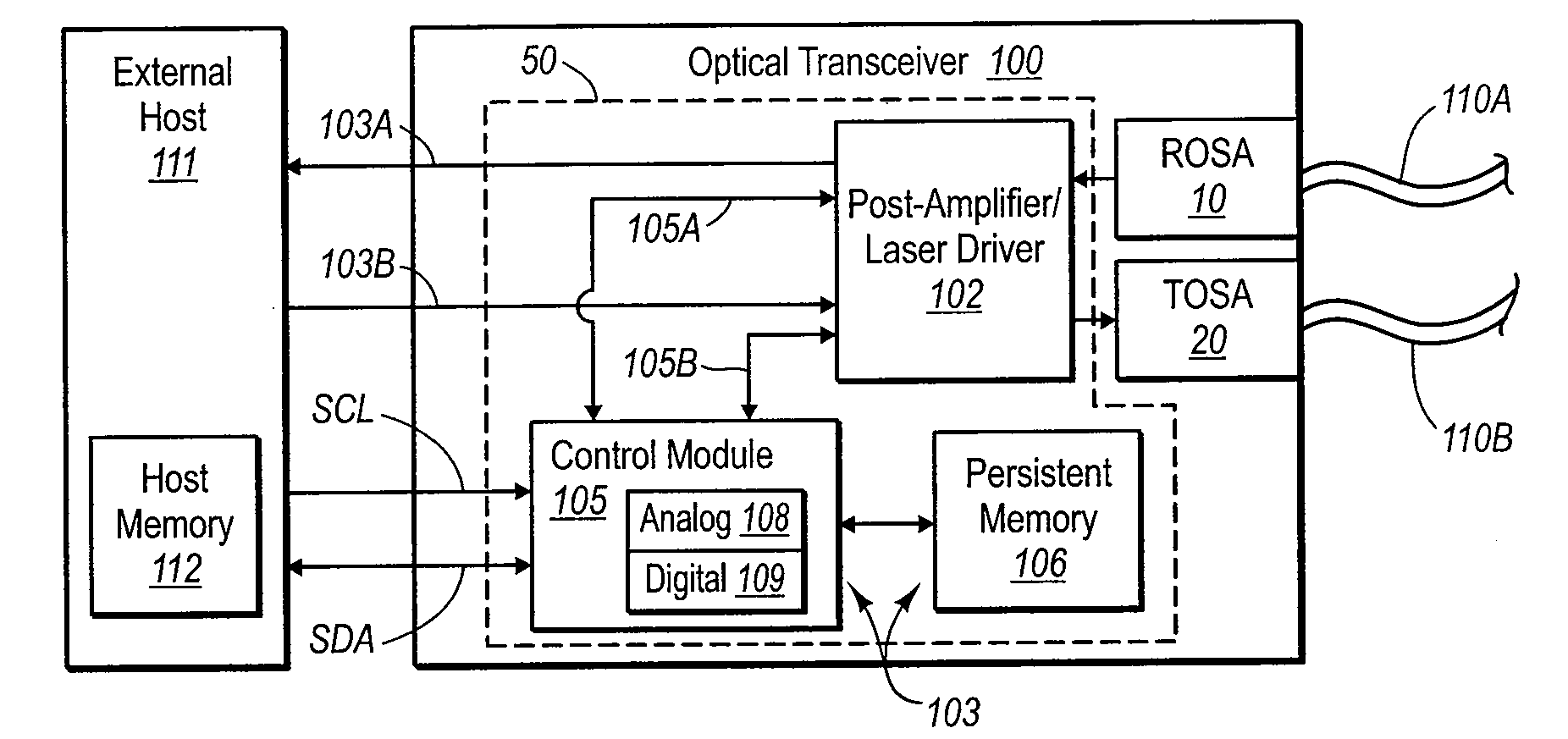
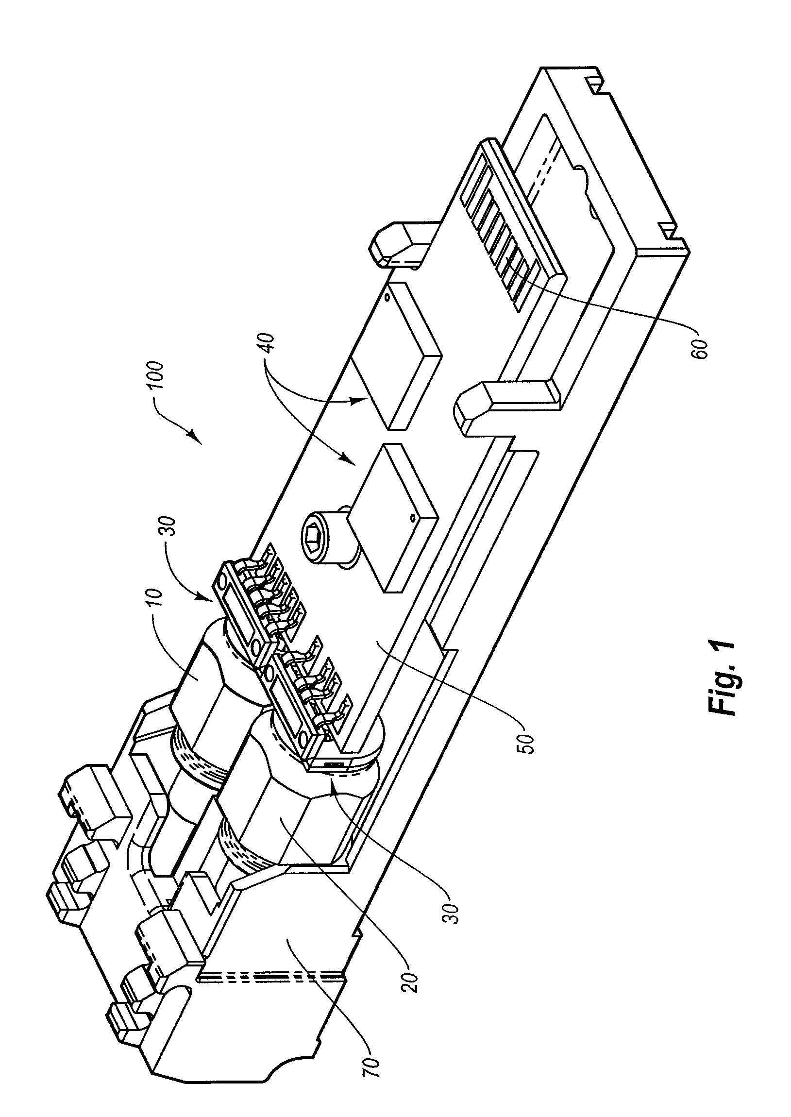
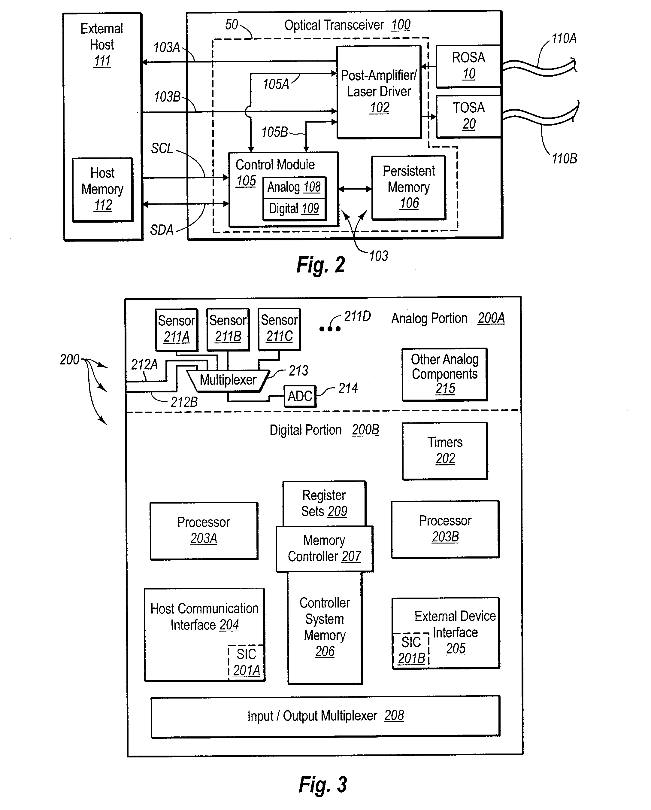
[0022]Reference will now be made to figures wherein like structures will be provided with like reference designations. It is understood that the drawings are diagrammatic and schematic representations of exemplary embodiments of the invention, and are not limiting of the present invention nor are they necessarily drawn to scale.

[0023]FIGS. 1-6 depict various features of embodiments of the present invention, which are generally directed to systems and methods for controlling the modulation current of a laser included as a component of an optical transmitter, such as an optical transceiver module. Control of the modulation current, which affects various laser operational parameters including extinction ratio and optical modulation amplitude, enables operation of the laser to be optimized, thereby enabling reliable transceiver performance to be achieved.

[0024]In the exemplary embodiments to follow, the laser is included in a transmitter optical subassembly (“TOSA”) of an optical transc...


PUM


Abstract

Systems and methods for controlling the modulation current of a laser included as a component of an optical transmitter, such as an optical transceiver module, are disclosed. Control of the modulation current, which affects various laser operational parameters, including extinction ratio and optical modulation amplitude, enables operation of the laser to be optimized, thereby enabling reliable transceiver performance to be achieved. In one embodiment, a method for modifying the modulation current in an optical transceiver module includes first sensing analog voltage data that proportionally relates to an actual modulation current of the laser. Once sensed, the analog voltage data are converted to digital voltage data. Using the digital voltage data, the actual modulation current of the laser is determined, then a desired modulation current is determined. Should a discrepancy exist between the actual and desired modulation currents, the actual modulation current is modified to match the desired current.

Description

CROSS-REFERENCE TO RELATED APPLICATIONS[0001]This application claims the benefit of U.S. Provisional Application No. 60 / 825,603, filed Sep. 14, 2006, which is incorporated herein by reference in its entirety.BACKGROUND[0002]1. Technology Field[0003]The present invention generally relates to optical transmitters. In particular, the present invention relates to an optical transmitter capable of measuring and compensating for the modulation current of a laser included in the transmitter such that an optical signal having sufficient optical characteristics is produced.[0004]2. The Related Technology[0005]A properly operating light source is integral to functionality of an optical transmitter. Such light sources, including a laser diode positioned in a transmitter optical subassembly of an optical transceiver module for example, should conform to pre-defined parameters propounded by the manufacturer or applicable industry. These pre-defined parameters involve various characteristics of t...

Claims


Application Information

Patent Timeline
Patent Type & Authority Applications(United States)
IPC IPC(8): H04B10/12H04B10/00H04B10/04
CPCH04B10/504H04B10/40
Inventor NELSON, STEPHEN T.MORAN, TIMOTHY G.
Owner II VI DELAWARE INC
Learn More