

Fixing device and image forming apparatus
a technology of fixing device and image forming apparatus, which is applied in the direction of electrographic process apparatus, instruments, optics, etc., can solve the problem of reducing the fixing property
- Summary
- Abstract
- Description
- Claims
- Application Information
AI Technical Summary
Benefits of technology
Problems solved by technology
Method used
Image

Examples
first embodiment
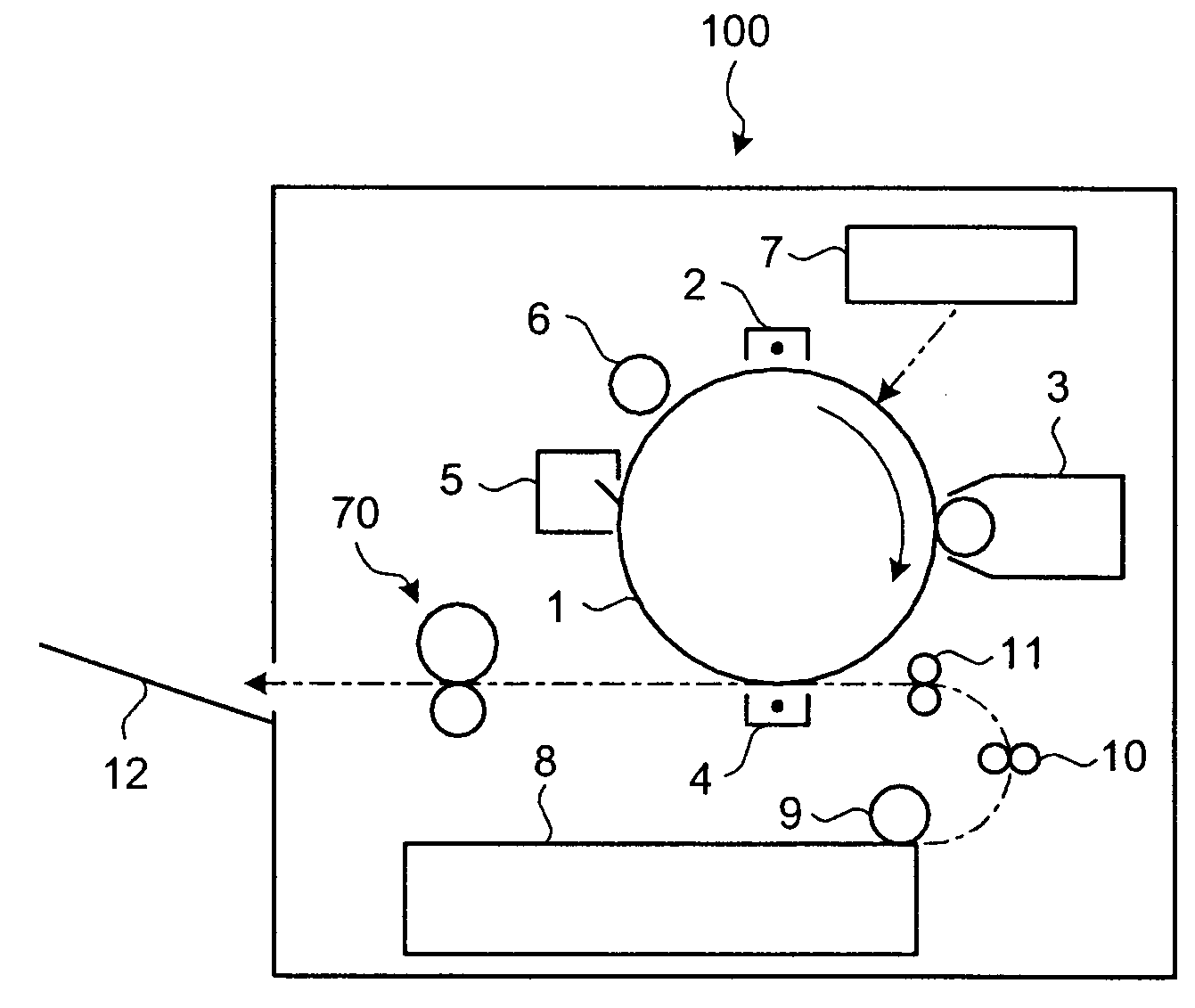
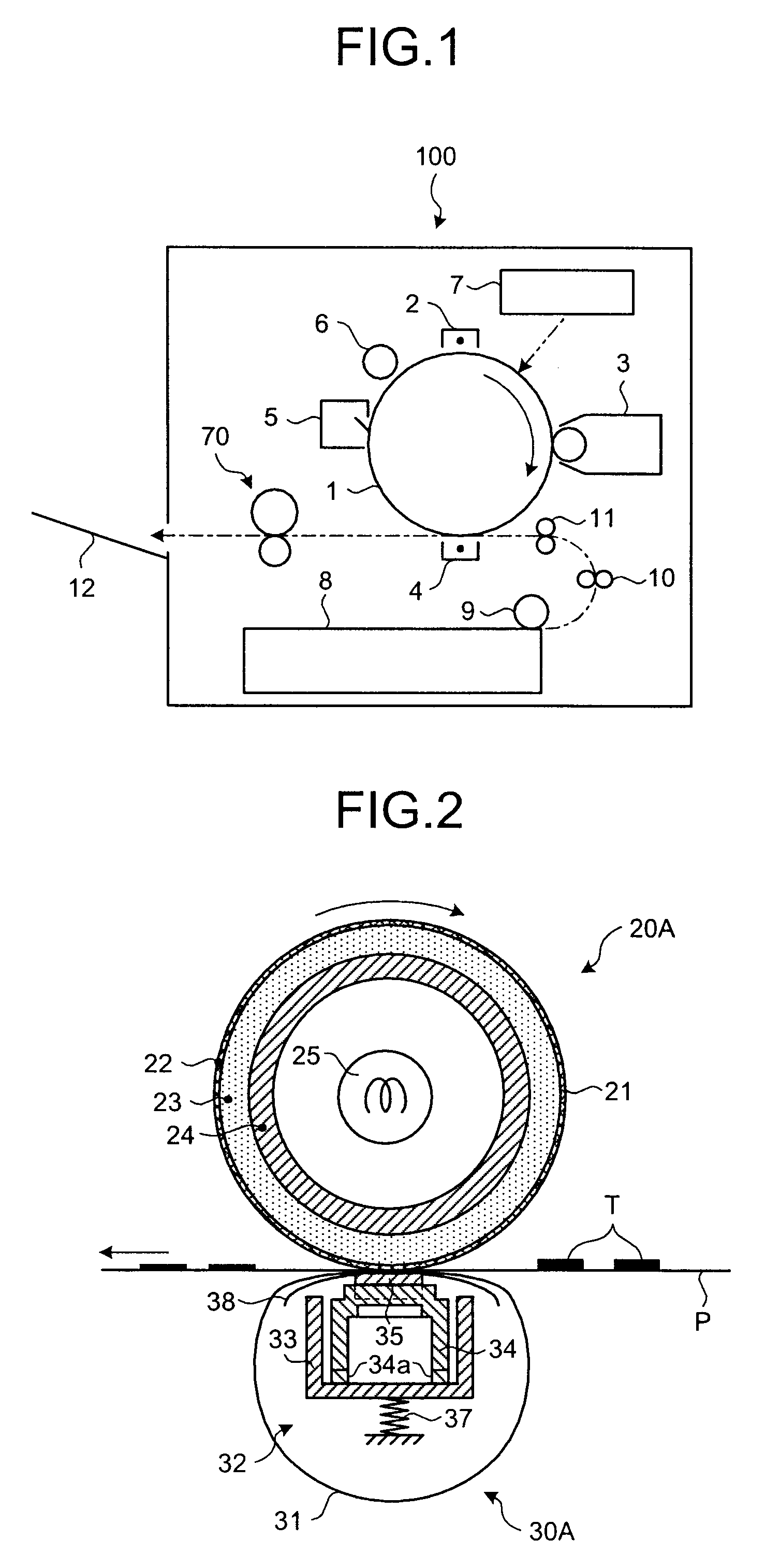
[0029]FIG. 1 is a schematic diagram of a laser printer 100 as an example of an image forming apparatus that includes a fixing device according to the present invention. The laser printer 100 includes a photosensitive drum 1 serving as an image carrier. Around the photosensitive drum 1 are arranged a charging unit 2, a developing device 3, a transfer unit 4, a cleaning unit 5, and an discharging unit 6. A writing device 7 is arranged above the photosensitive drum 1, and emits laser writing beams to an exposure portion of the photosensitive drum 1 between the charging unit 2 and the developing device 3.
[0030]A sheet cassette 8 is arranged at the bottom of the image forming apparatus. A feed roller 9, a pair of conveyor rollers 10, and a pair of registration rollers 11 that are arranged to feed sheets from the sheet cassette 8. A fixing device 70 is arranged in a lateral direction of a transfer portion in which the photosensitive drum 1 and the transfer unit 4 face each other.
[0031]The...
second embodiment
[0045]FIG. 7 is a side view of a fixing device according to the present invention. Like reference characters refer to corresponding portions throughout the drawings.
[0046]The fixing device includes a fixing unit 20B and the pressure unit 30A. The fixing unit 20B is basically the same as the fixing unit 20A except that it includes control members 26 to prevent the elastic layer 23 from being deformed in the axial direction. The pressure unit 30A is the same as that shown in FIGS. 2 and 3.
[0047]The control members 26 of the fixing device are ring-shaped, fitted and fixed to the cored bar 24, and rotate with the heat roller 21. Thus, the control members 26 are static with respect to the elastic layer 23, i.e., they do not move relative to the elastic layer 23. The control members 26 are arranged adjacent to ends of the elastic layer 23 in the axial direction, and control deformation of the elastic layer 23 in the axial direction. The control members 26 can be formed integrally with the...
third embodiment
[0049]FIG. 8 is a side view of a fixing device according to the present invention, and depicts a sectional view of the heat roller 21. The fixing heater 25 thereof is omitted.
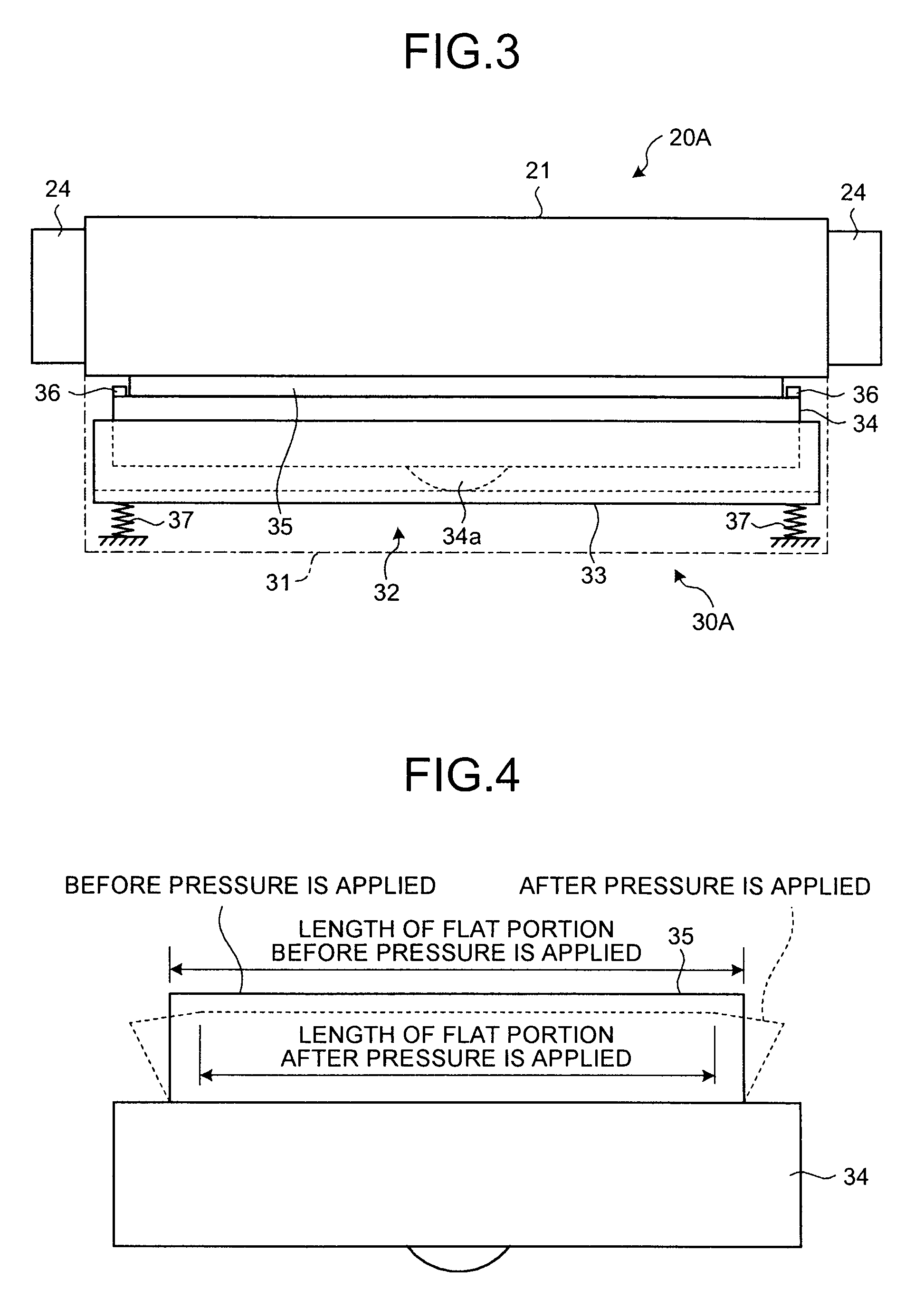
[0050]The fixing device includes the fixing unit 20A and a pressure unit 30B. The fixing unit 20A is the same as that shown in FIGS. 2 and 3. The pressure unit 30B is basically similar to pressure unit 30A except that the pressure pad 35 has substantially the same width in the axial direction as that of the elastic layer 23. Accordingly, the holder 34 and the stay 33 are increased in width. While the fixing device of the third embodiment includes the control guides 36 that control deformation of the pressure pad 35 in the axial direction, it does not include control members that control deformation of the elastic layer 23 in the axial direction. However, the fixing unit 20A comes into pressure-contact with the pressure unit 30B so that the pressure pad 35 and the elastic layer 23 are in close contact with each ...
PUM
 Abstract
Description
Claims
Application Information