Wind Turbine Blades Made of Two Separate Sections, and Method of Assembly

a technology sections, applied in the field can solve the problems of low strength and rigidity, the erecting process of wind turbines is still complicated, and the transport of wind turbine blades adds challenges and costs to the process of erecting wind turbines, so as to enhance or accelerate the bonding process, enhance the precision of the section positioning process, and strengthen the adhesive connection

Active Publication Date: 2008-03-20
VESTAS WIND SYST AS
View PDF8 Cites 134 Cited by
  • Summary
  • Abstract
  • Description
  • Claims
  • Application Information

AI Technical Summary

Benefits of technology

[0044] The assembly plant is advantageous as it may establish the necessary surroundings in order to connect the wind turbine blade sections at the place of erecting the wind turbines or at a nearby place e.g. at a local plant. The necessary means are all such that they may be transported to the place with one or a few trucks and subsequently be dismantled and moved to a new place.
[0045] In an aspect of the invention, said means for controlling one or more environmental values include a heat supply and humidity control, sensors e.g. temperature and humidity sensors and control means for controlling the adhesive process. By controlling the temperature and humidity it is possible to enhance or accelerate the bonding process and thus create a stronger adhesive connection between the sections.
[0046] In an aspect of the invention, said means to position the wind turbine blade sections ...

Problems solved by technology

However, the increasing size of modern wind turbines has also resulted in still longer and heavier wind turbine blades.
Consequently, transport of wind turbine blades adds challenges and costs to the process...

Method used


Image

  • Wind Turbine Blades Made of Two Separate Sections, and Method of Assembly
  • Wind Turbine Blades Made of Two Separate Sections, and Method of Assembly
  • Wind Turbine Blades Made of Two Separate Sections, and Method of Assembly

Examples


Embodiment Construction

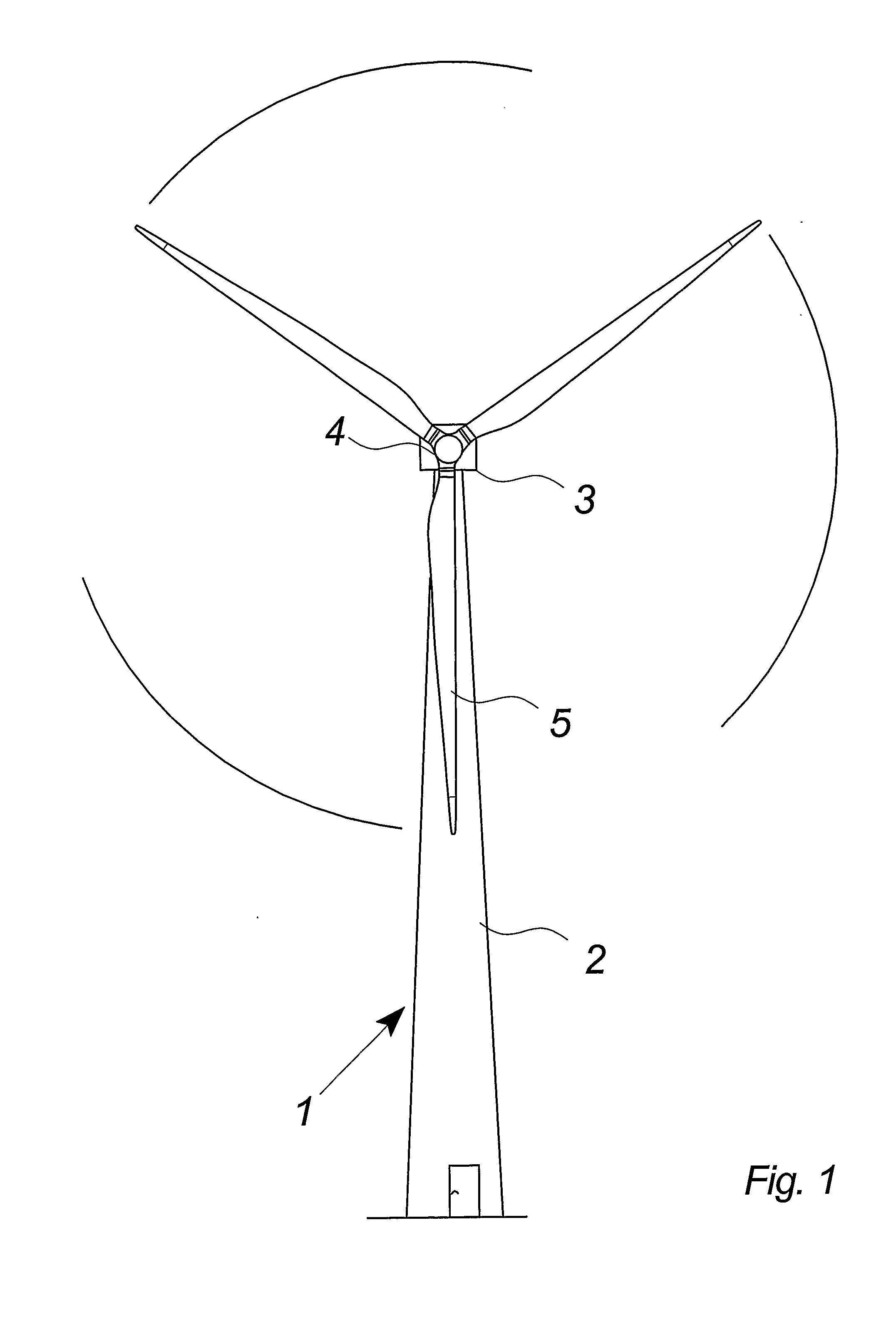
[0067]FIG. 1 illustrates a modern wind turbine 1 with a tower 2 and a wind turbine nacelle 3 positioned on top of the tower. The blades 5 of the wind turbine rotor are connected to the nacelle through the low speed shaft which extends out of the nacelle front.

[0068] As illustrated in the figure, wind over a certain level will activate the rotor and allow it to rotate in a perpendicular direction to the wind. The rotation movement is converted to electric power which usually is supplied to the transmission grid as will be known by skilled persons within the area.

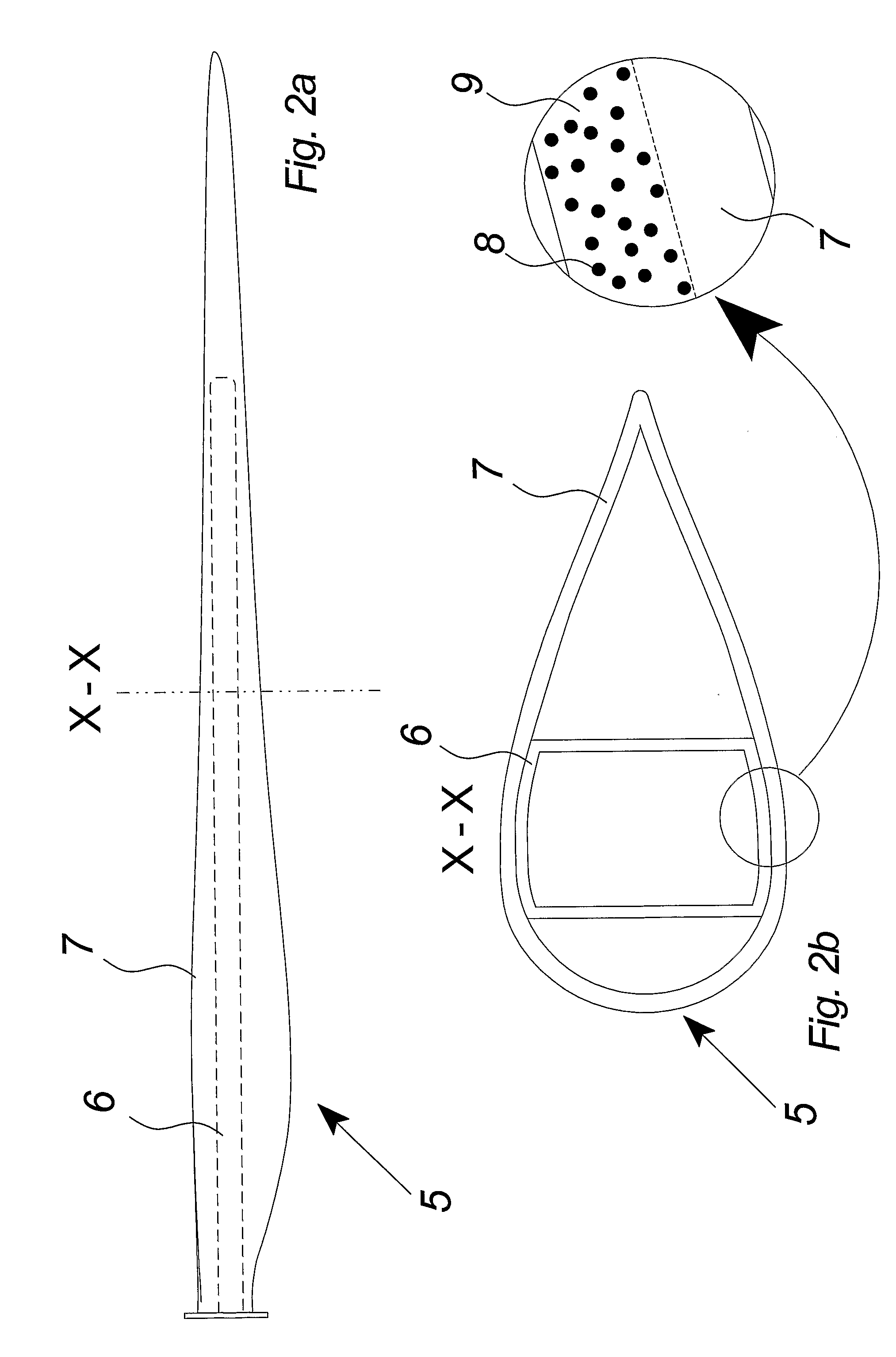
[0069]FIGS. 2a and 2b illustrate a wind turbine blade with an internal strengthening structure 6 and an enlarged cross sectional view of the blade.

[0070]FIG. 2a illustrates schematically how the internal strengthening structure 6 includes an internal beam structure which is directed from the root of the wind turbine blade 5 toward the tip of the blade. The beam structure is connected directly to the root flange in which th...


PUM

PropertyMeasurementUnit
Temperatureaaaaaaaaaa
Thicknessaaaaaaaaaa
Lengthaaaaaaaaaa

Abstract

The invention relates to a wind turbine blade (5) comprising at least two wind turbine blade sections (12, 13) that include one or more strengthening structures (6, 6a, 6b), the ends (14, 15) of said strengthening structures being connected in a connection joint. The ends include corresponding connection surfaces, the one or more relevant dimensions of said surfaces being larger than the dimensions of the transverse surfaces of the strengthening structures at said ends. The one or more relevant dimensions of said connection joint are larger than that of the adjacent strengthening structure. The invention also relates to a wind turbine blade in which the at least two wind turbine blade sections include a number of substantially oblong carbon fiber strips and strips of one or further materials such as wood or glass fiber. The invention further relates to a wind turbine blade section, an assembly plant for assembling wind turbine blade sections (12, 13) and to a method and use of such wind turbine blades.

Description

BACKGROUND OF THE INVENTION [0001] The invention relates to wind turbine blades, a wind turbine section, method and use hereof. DESCRIPTION OF THE RELATED ART [0002] Wind turbine blades are very important components in a modern wind turbine and are highly important in defining the energy production and the lifespan of the wind turbine. However, the increasing size of modern wind turbines has also resulted in still longer and heavier wind turbine blades. The transport of the blades from the place of production to the place of erecting the wind turbine is thus a matter that requires a lot of consideration e.g. in choosing the right routes in relation to the characteristics of the blade such as the length, height and weight of the blade. Further, the transport requires more and more specialized equipment in handling the wind turbine blades. [0003] Consequently, transport of wind turbine blades adds challenges and costs to the process of erecting wind turbines. [0004] The prior art incl...

Claims


Application Information

Patent Timeline
IPC IPC(8): F01D5/14
CPCB29C66/20Y10T29/49336B29C66/721B29C66/9121B29C66/9141B29K2105/101B29K2307/00B29K2309/08B29L2031/08B29L2031/085B29L2031/7504F03D1/0675F05B2230/23F05B2240/302Y02E10/721B29C66/223B29C66/961B29C66/9534B29C66/54B29C66/9161B29C65/00B29C66/72141B29C66/71B29C66/7212B29C66/7254B29C65/4815B29C65/483B29C66/1162B29C66/1142Y02E10/72Y02P70/50B29C70/304B29K2063/00B29K2307/04
Inventor BECH, ANTON
Owner VESTAS WIND SYST AS
Why Eureka
Try Eureka