Positive displacement pump apparatus and method

a technology of displacement pump and displacement pump, which is applied in the direction of positive displacement pump, liquid fuel pump, piston pump, etc., to achieve the effect of facilitating material movement, facilitating material movement, and facilitating material movemen

Active Publication Date: 2008-03-20
SPX FLOW INC
View PDF5 Cites 31 Cited by
  • Summary
  • Abstract
  • Description
  • Claims
  • Application Information

AI Technical Summary

Benefits of technology

[0016] In one aspect, a pump is provided having a front cover, a rotor body forming a chamber with the front cover and having an inlet port and an outlet port, a pair of drive shafts, a gear case supporting the pair of drive shafts, and a pair of rotors disposed in the chamber, wherein the front cover forming the front of the rotor chamber has a contoured inner relief region located adjacent one of the inlet port and the outlet port, and located next to the front of the rotor swept area to facilitate movement of material through the pumped rotor area.
[0017] In another aspect, a pump is provided having a front cover, enclosure means for forming a chamber with the front cover and having an inlet port and an outlet port, a pair of drive shafts, means for supporting the pair of drive shafts, and a pair of rotors disposed in the chamber, wherein the front cover formi...

Problems solved by technology

Usually, such pumps are subject to cleaning procedures, and also s...

Method used


Image

  • Positive displacement pump apparatus and method
  • Positive displacement pump apparatus and method
  • Positive displacement pump apparatus and method

Examples


Embodiment Construction

[0045] Some embodiments of the present invention provide an improved positive displacement rotary pump apparatus and method. Examples will be discussed below with reference to the drawing figures in which like reference numerals refer to like parts throughout.

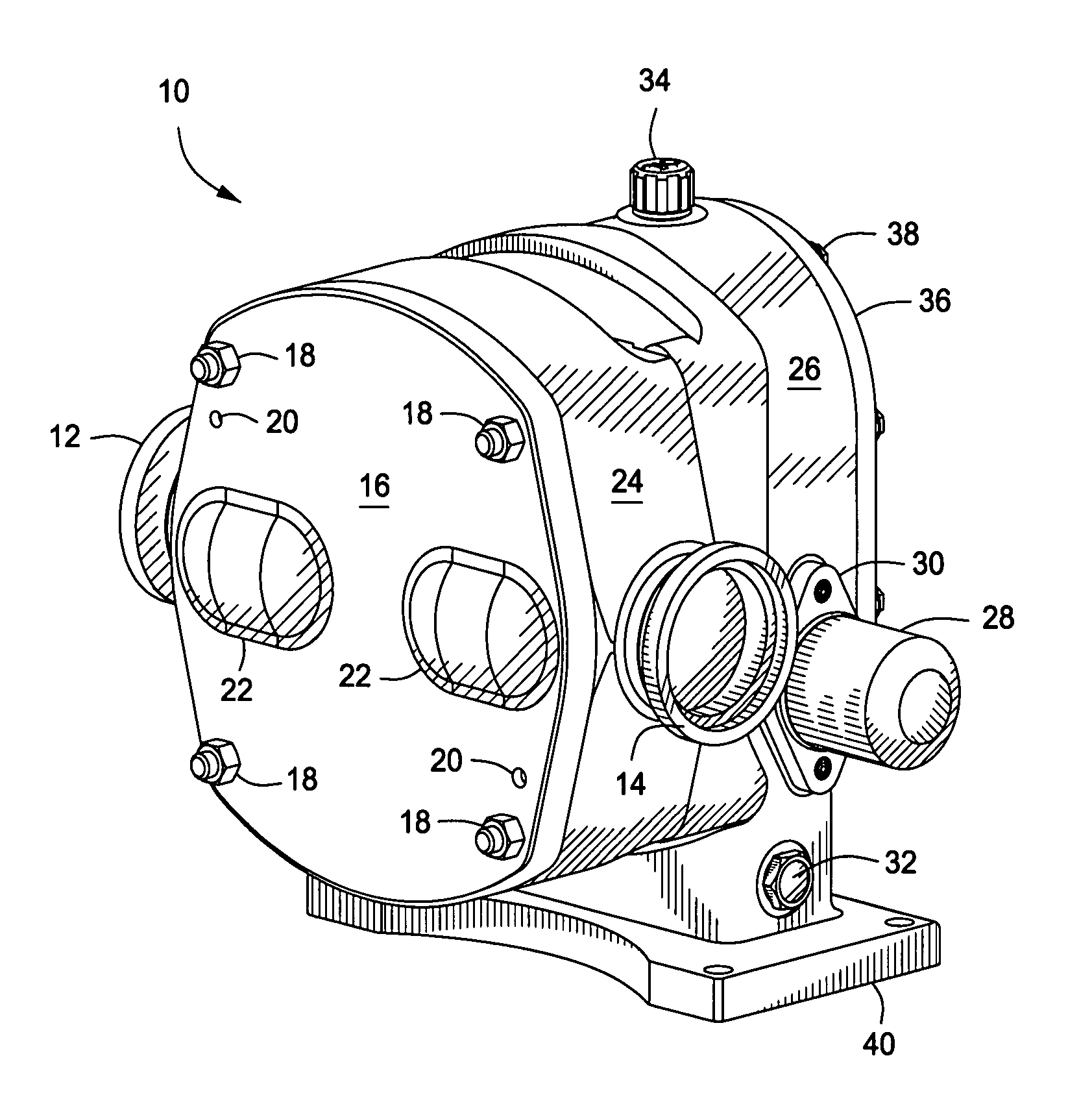
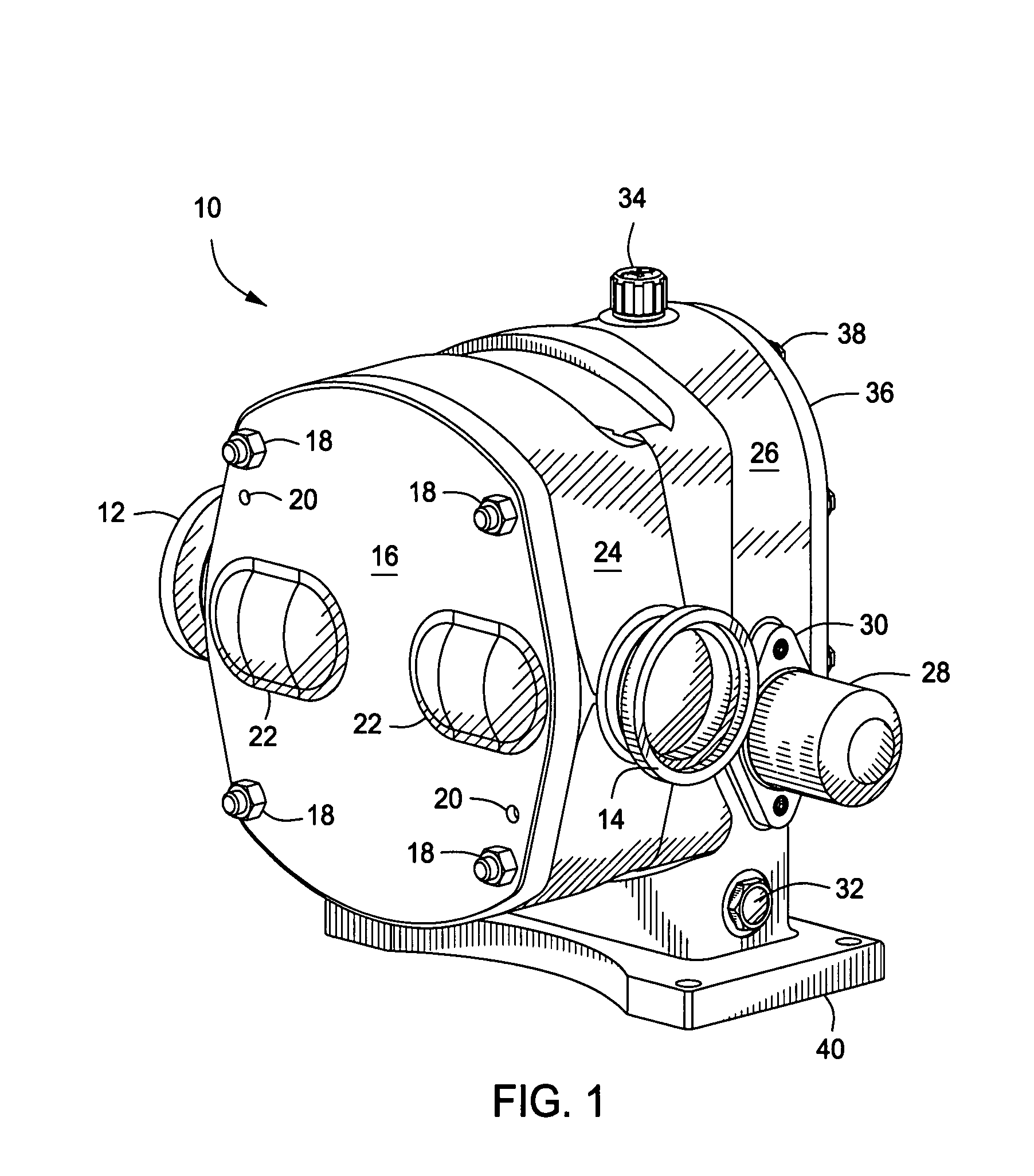
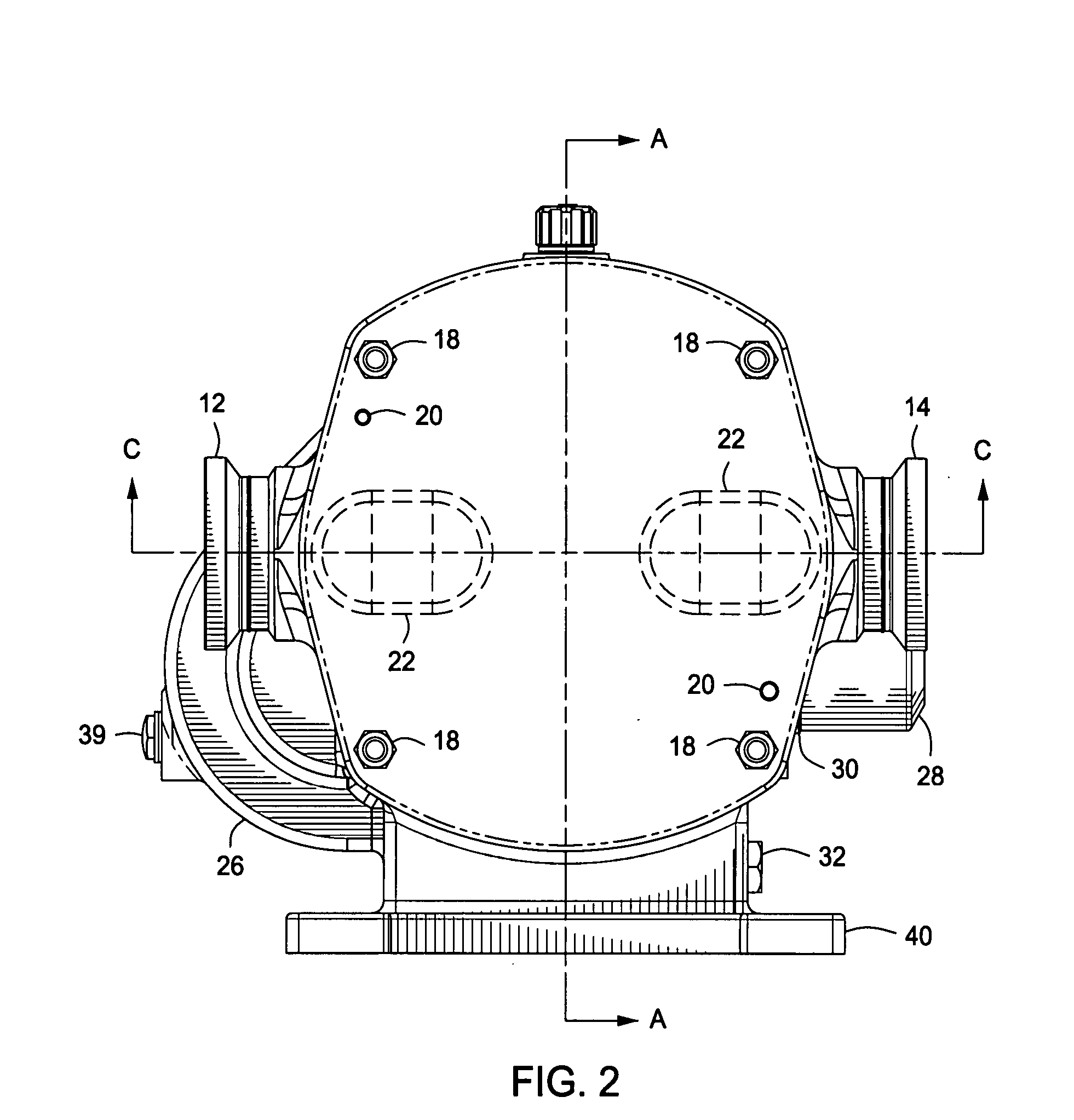
[0046]FIGS. 1 and 2 illustrate a pump 10 having an inlet port 12 and an outlet port 14. The illustrated embodiment is bi-directional, in that it can pump in either direction, so the selection of inlet and outlet is given for example only in this description. Changing direction of the pump is accomplished simply by changing the direction of rotation of the motor or gear reducer that is driving the pump. The pump has a front cover 16 mounted by a series of bolts 18, and alignment features such as dowel pin holes 20, to a body 24. The dowel pins and holes 20 serve to align the front cover 16 with the body 24.

[0047] The front cover 16 and body 24 substantially define an internal chamber for the internal rotors which are not visib...


PUM


Abstract

An improved positive displacement rotary pump apparatus and method is provided including a front cover, a rotor body forming a chamber with the front cover, a gear case supporting a pair of hollow drive shafts, and a pair of rotors disposed in the chambers and each detachably mounted to one end of a respective hollow drive shaft via a stud that extends from the rotor through the hollow shaft to a fastener. The pump can also have at least one respective face seal between each rotor and the body with at least one first rotating seal ring disposed at the backward facing face of each rotor, and at least one respective second stationary rotating seal ring disposed on a forward facing face of the pump body. The pump further has a pair of bearings that rotatably support the shaft in the gear case, with each bearing being located relative to the gear case by a respective locating ring that is axially movable relative to the gear case, so that each bearing is axially adjustable relative to the gear case. The pump also has a contoured inner relief region located adjacent one of the inlet port and the outlet port, and located next to the front of the rotor swept area to facilitate movement of material through the pumped rotor area

Description

CROSS REFERENCE TO RELATED APPLICATIONS [0001] This application claims priority to Provisional Patent Application Ser. No. 60 / 836,122 filed Aug. 8, 2006, the entire disclosure of which is hereby incorporated herein by reference in its entirety.BACKGROUND OF THE INVENTION [0002] Pumps are in wide use in industry. One popular type of pump for certain applications is known as a rotary positive displacement pump. Such pumps have two counter-rotating rotors that form a moving entrapped volume between the rotor and the inside of a stationary body forming a chamber inside which the rotors move, thus forcing the material from an inlet on the body to an outlet on the body. This type of pump has many applications including for example in the processing of food, chemicals, paint, cosmetics and other materials. In some cases the rotors have intermeshing lobes. In other designs the rotors have wing shaped projections that form moving circumferential pistons together with the inside of a swept bo...

Claims


Application Information

Patent Timeline
IPC IPC(8): F04B35/04
CPCF01C21/02F04C2/086F04C2250/10F04C13/005F04C2/123
Inventor VAN NORMAN, DREWHAGEN, CURT
Owner SPX FLOW INC
Why Eureka
Try Eureka