

Continuously variable drivetrain
a drivetrain and continuous variable technology, applied in the direction of cycle equipment, gymnastics, gearing, etc., can solve the problems of linear drive systems in human powered vehicles, ineffective as commonly used drivetrains, and the loss of kinetic energy of drivetrains
- Summary
- Abstract
- Description
- Claims
- Application Information
AI Technical Summary
Benefits of technology
Problems solved by technology
Method used
Image

Examples
Embodiment Construction
” one will understand how the features of the system and methods provide several advantages over traditional systems and methods.
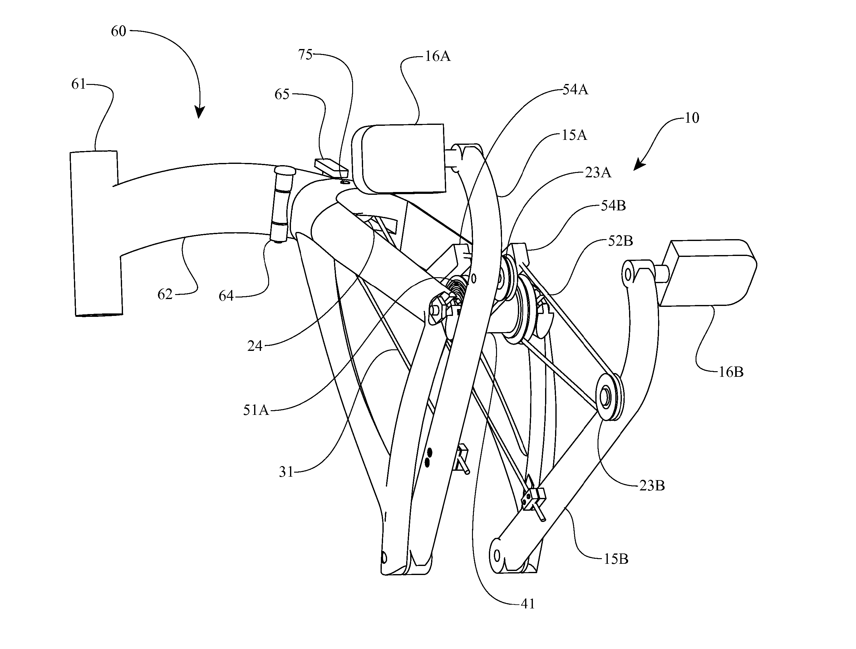
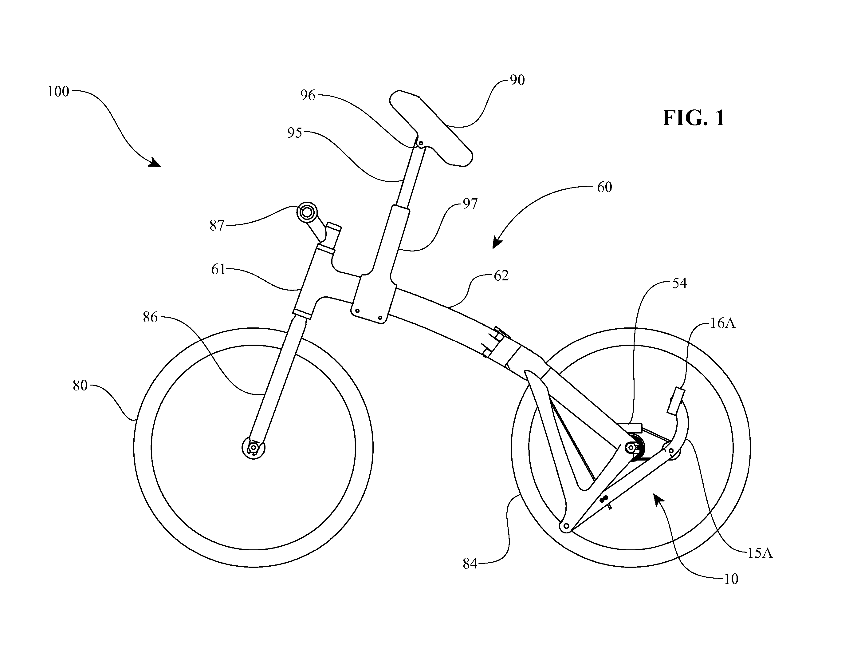
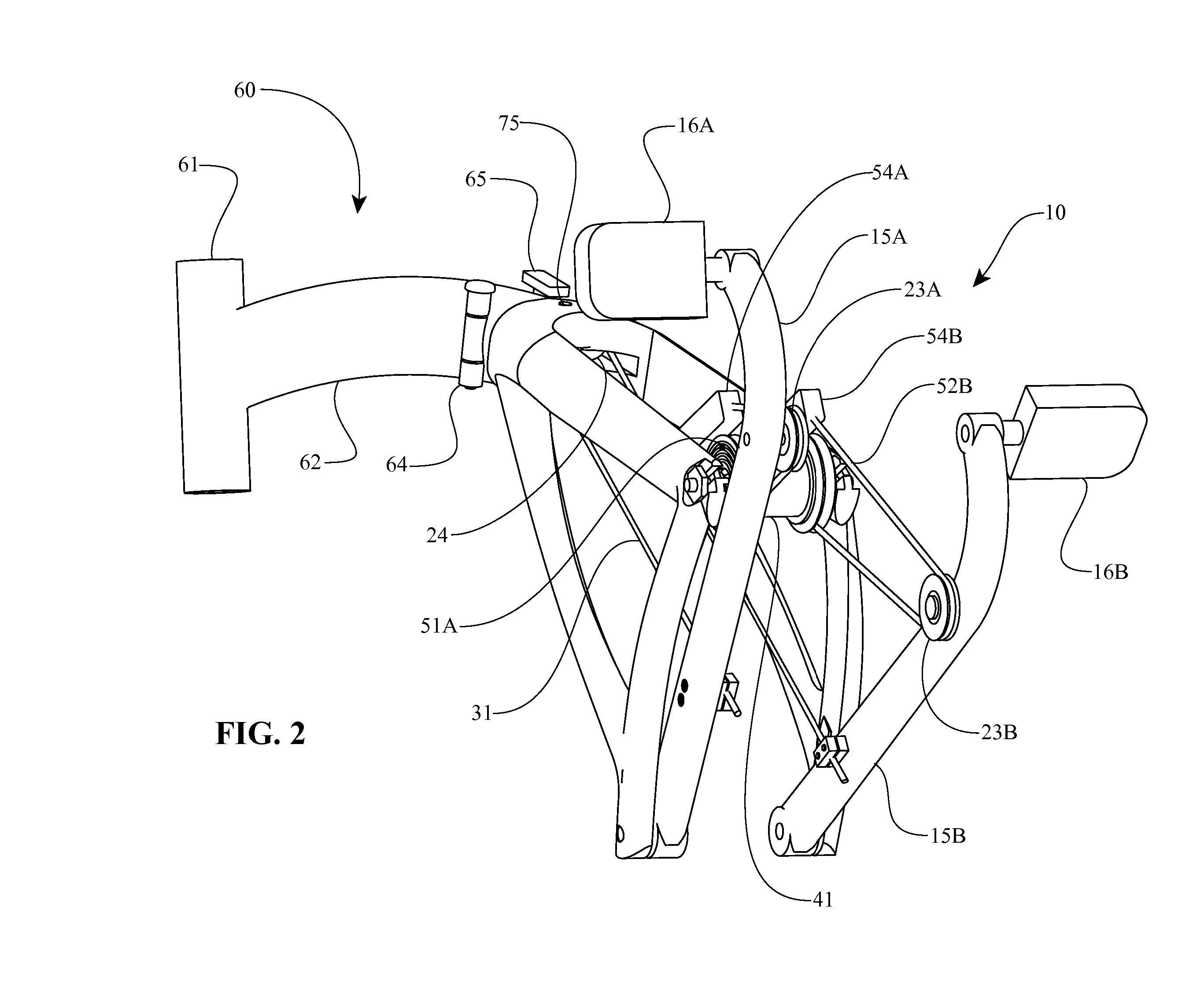
[0015] In one aspect, a pulley and cable drivetrain is disclosed which continuously varies speed and torque throughout its stroke. In some systems the continuously variable drivetrain incorporates two pedals, which are contacted by a person's feet, and move in reciprocating motion to transmit power. Each pedal attaches to a crank which rotates along an arc defined by a pivot point at an end opposite the pedal. The cranks attach to a frame, which in some systems comprises the support structure for a human powered vehicle or exercise equipment. Also attached to each crank is a pulley, the pulley positioned at a distance from the crank pivot point to produce the correct rotational speed of a drive pulley. The drive pulley, of which there is one for each crank, has a drive cable wrapped around a deep annular groove. The drive cable terminates at the interior o...
PUM
 Abstract
Description
Claims
Application Information