
Liquid atomizer

a technology of liquid atomizer and atomizer, which is applied in the direction of liquid spraying apparatus, spray nozzle, moving spraying apparatus, etc., can solve the problems of increasing noise, consuming too much power, and requiring fans, and achieve the effect of reducing nois

Active Publication Date: 2008-03-27
MICRO BASE TECH CORP
View PDF4 Cites 18 Cited by
  • Summary
  • Abstract
  • Description
  • Claims
  • Application Information

AI Technical Summary

Benefits of technology

[0009]The object of the present invention is to provide a liquid atomizer that reduces noise.
[0010]Another object of the present invention is to provide a liquid atomizer that enhances the service life of spray plate.
[0011]A further object of the present invention is to provide a liquid atomizer that prevents the working frequency drift.
[0012]Yet another object of the present invention is to provide a liquid atomizer that improves atomization efficiency.

Problems solved by technology

But pressure-type atomizer requires machine for pressurization, and generates greater noise.
Thus the medical application of pressure-type atomizer gradually loses its appeal.
But it also has the drawbacks of consuming too much power and requiring fans to direct the flow of droplet mist.
The former requires greater energy to drive the piezoelectric material in order to atomize the liquid and generate smaller droplets, and is less efficient as compared to the latter.
The latter contains spray plate, which is an active vibration component prone to fatigue.
Other problems associated with the latter type of piezoelectric atomizers include noise during liquidless air vibration, reduced service life of spray plate in case of large-area vibration, working frequency drift following air vibration, and low atomization efficiency.
Because of increase in its vibration area, the spray plate tends to fatigue easily, and increase in the spray plate load reduces the atomization efficiency.

Method used


Image

  • Liquid atomizer
  • Liquid atomizer
  • Liquid atomizer

Examples


Embodiment Construction

[0028]The present invention will be fully described with preferred embodiments and accompanying drawings. It should be understood beforehand that any person familiar with the skill is able to make modification to the invention described and attain the same effect, and that the description below is a general representation to people familiar with the skill and should not be construed as a limitation on the actual applicable scope of the present invention.

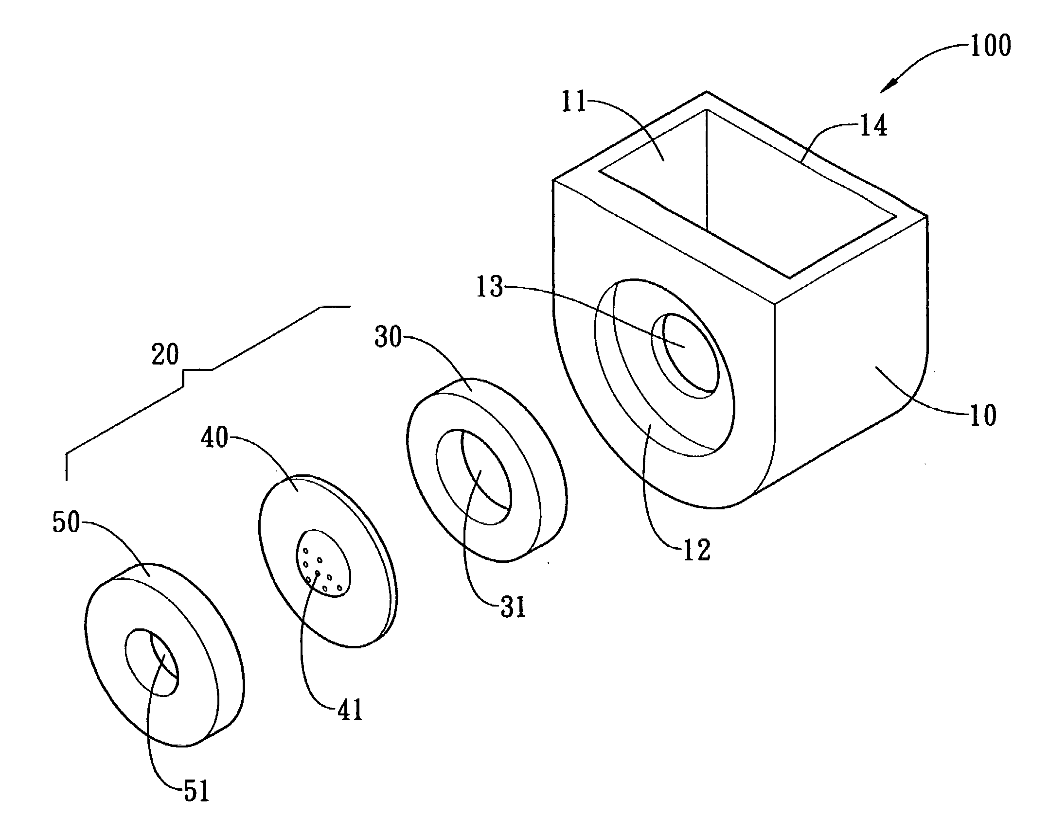
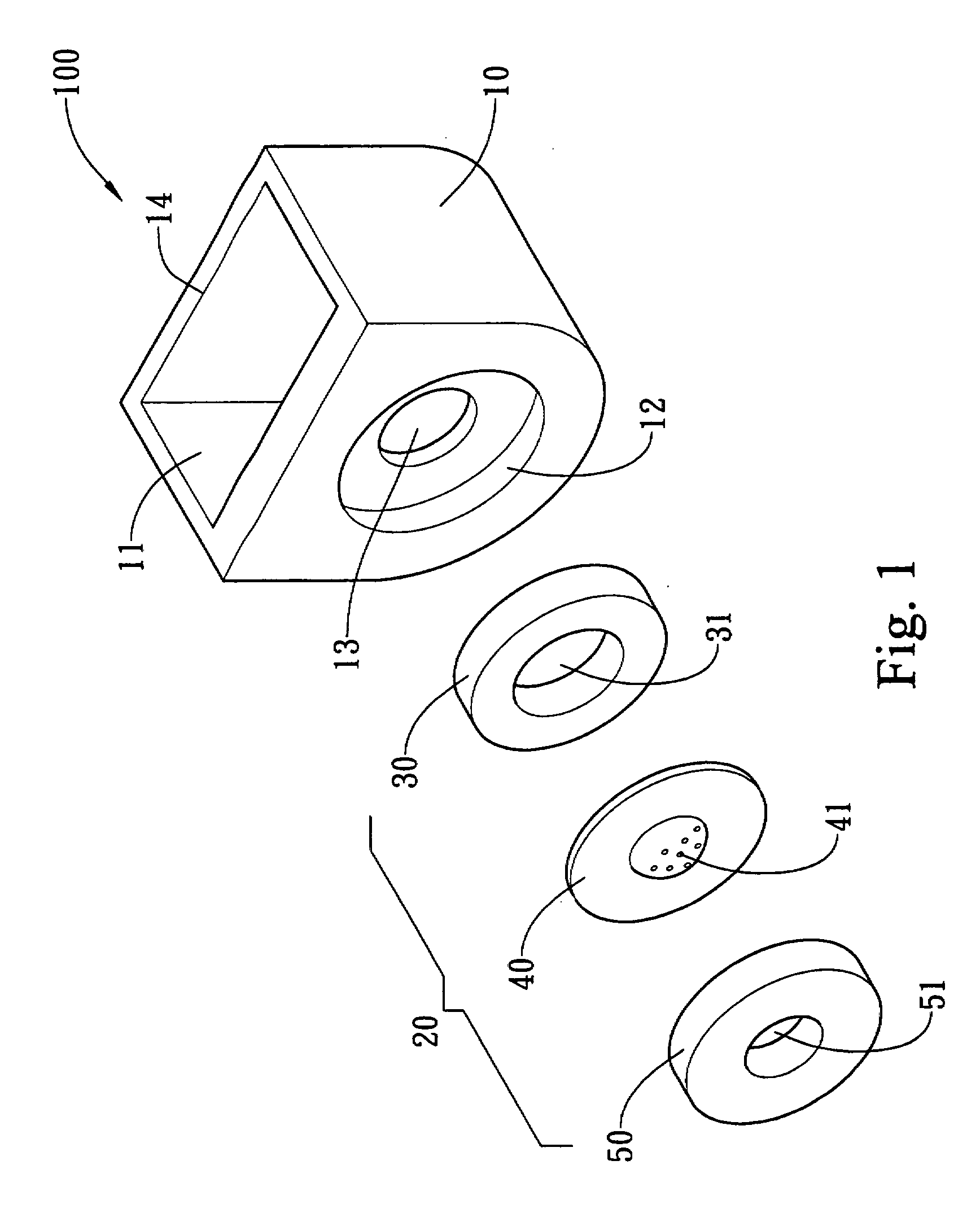
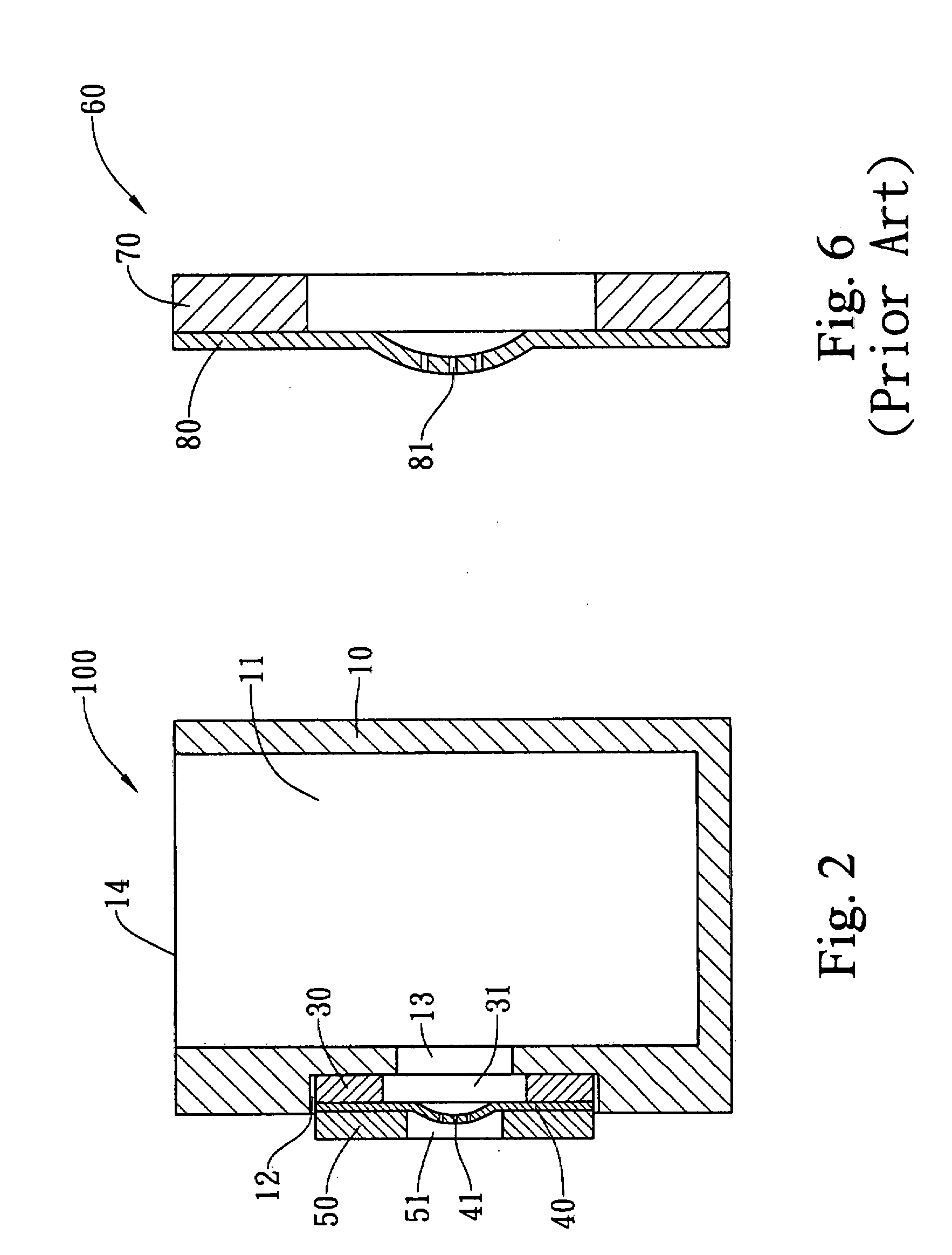
[0029]FIG. 1 shows the exploded perspective view of a liquid atomizer of the present invention applied in an atomizing device. The liquid atomizer 20 of the present invention comprises a vibrating element 30, a spray plate 40, and a structure element 50. The atomizing device includes a body 10 having a cavity 11 for storing liquid to be atomized (not shown in the figure) and an accommodating space 12 and a through hole 13 provided on one side of the body 10. The liquid atomizer 20 is disposed inside the accommodating space 12 of body...


PUM


Abstract

The present invention provides a liquid atomizer for atomizing liquid and applied in an atomizing device having an accommodating space and a through hole. The liquid atomizer includes a vibrating element having a first hole corresponding to the through hole; a spray plate having a plurality of spraying holes corresponding to the first hole and being connected with the vibrating element; and a structure element having a second hole corresponding to the plurality of spraying holes of the spray plate and being connected with the spray plate so that the spray plate is disposed between the vibrating element and the structure element. The vibrating element, the spray plate and the structure element are assembled in the accommodating space of the atomizing device. Liquids are atomized via the spraying holes of the spray plate.

Description

BACKGROUND OF THE INVENTION[0001]1. Field of the Invention[0002]The present invention relates to a liquid atomizer, more particularly a kind of liquid atomizer capable of reducing noise, improving the service life of spray plate, preventing working frequency drift, and enhancing the atomization efficiency.[0003]2. Description of the Related Art[0004]Liquid atomizer currently available on the market comes in pressure type and mechanical oscillation type. The former atomizes liquid using pressure gradient and is able to atomize large amount of liquid. But pressure-type atomizer requires machine for pressurization, and generates greater noise. For medical atomizer, only small amount of liquid needs to be atomized, but the size of droplet produced is an important consideration. Thus the medical application of pressure-type atomizer gradually loses its appeal. Mechanical oscillation type atomizer has been the dominant type of medical atomizer in recent years that largely uses ultrasonic ...

Claims


Application Information

Patent Timeline
IPC IPC(8): B05B1/00
CPCB05B17/0646
Inventor WANG, LIANG-DEWU, TAI-FENGCHEN, YI-CHENGWANG, YU-RANYEH, CHIEN-SHIENSHEN, SHENG-CHIH
Owner MICRO BASE TECH CORP
Learn More