Magnetic cores for inductors and transformers and method of manufacture

a technology of inductors and transformers, applied in the direction of magnetic cores of transformers/inductances, magnetic bodies, magnetic bodies, etc., can solve the problem of limiting the maximum practical frequency

Inactive Publication Date: 2008-03-27
GENERAL ELECTRIC CO
View PDF2 Cites 15 Cited by
  • Summary
  • Abstract
  • Description
  • Claims
  • Application Information

AI Technical Summary

Problems solved by technology

The eddy currents give rise to losses in the magneti...

Method used


Image

  • Magnetic cores for inductors and transformers and method of manufacture
  • Magnetic cores for inductors and transformers and method of manufacture
  • Magnetic cores for inductors and transformers and method of manufacture

Examples


Embodiment Construction

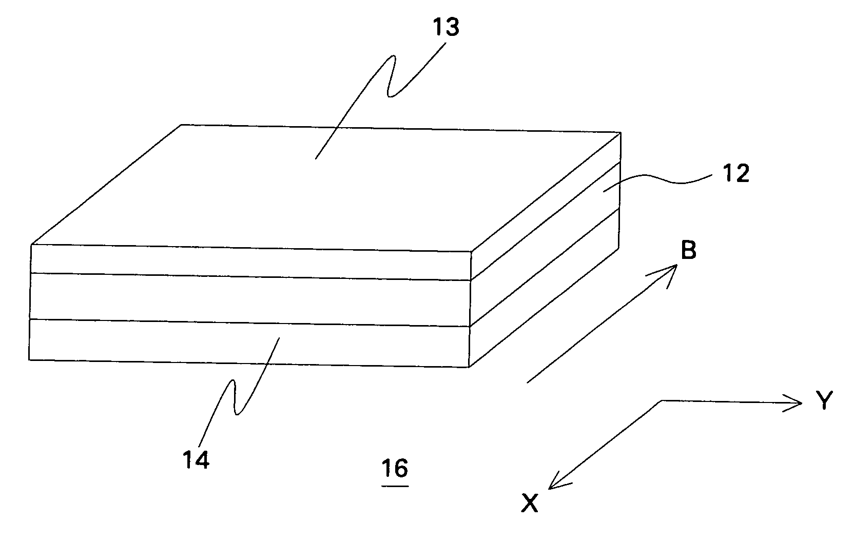
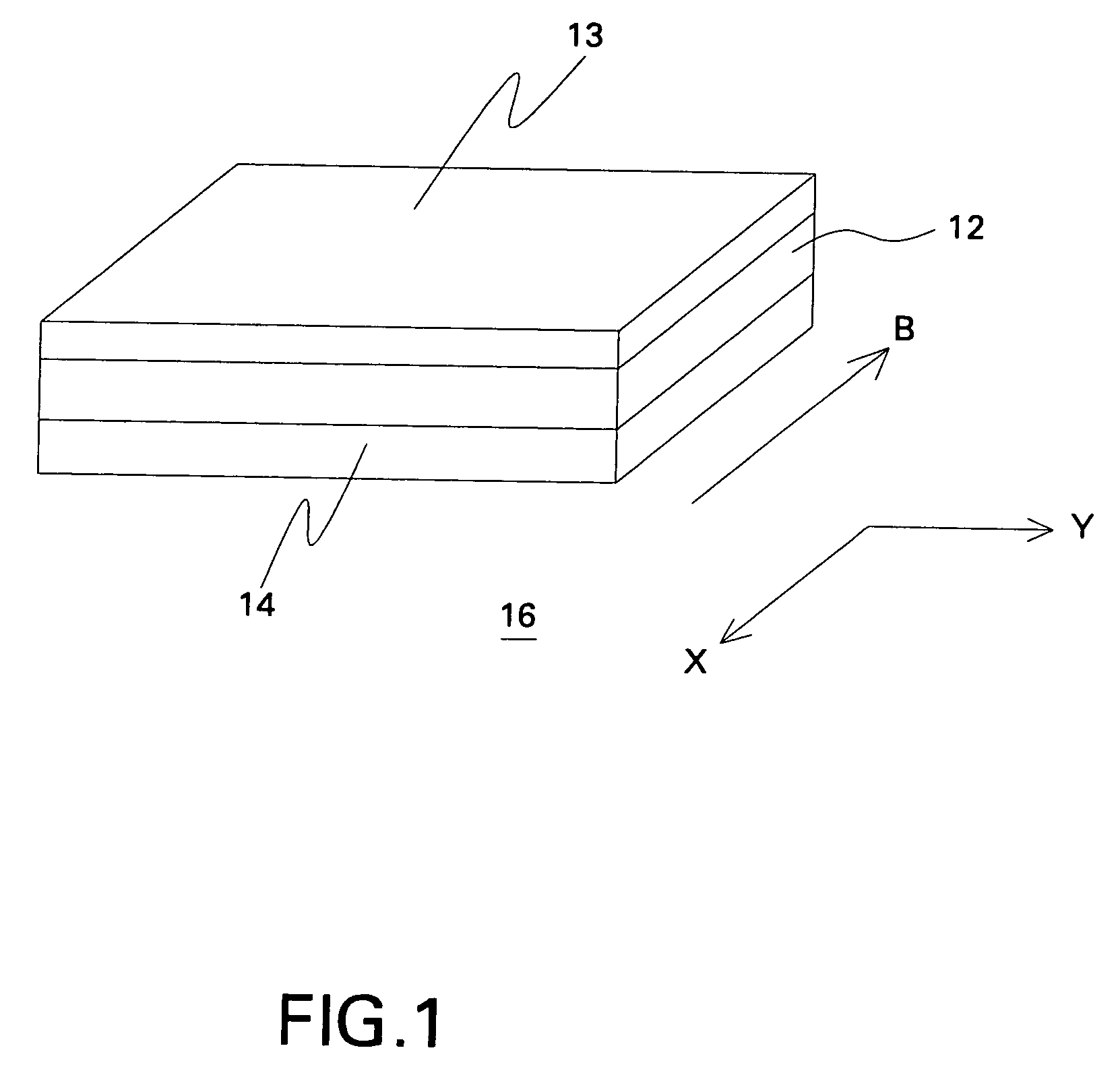
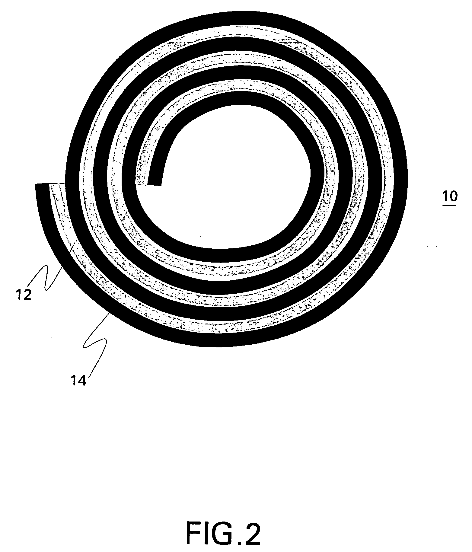
[0018]Embodiments of the invention directed to a magnetic core 10 for a transformer 20 or an inductor 30 are described with reference to FIGS. 1 and 2. As shown for example in FIG. 1, the magnetic core 10 includes a tape 16 comprising a magnetic film 12 disposed on a substrate 14. The magnetic material 12 may be deposited on all or on parts of the substrate 14. Thus, the magnetic film 12 may be continuous or segmented. The tape 16 is arranged in a winding comprising a number of turns to form the magnetic core10. The magnetic film comprises a soft magnetic material characterized by a coercivity of less than about ten Oersteds (10 Oe). For the example embodiment depicted in FIG. 2, the tape 16 is spirally wound into a coil. By forming the core 10 in this manner, the cross-section of the core 10 is effectively subdivided into a number of smaller sections of magnetic material 12 that are separated by sections of electrically non-conductive material 14, so that the bulk core 10 has a lam...


PUM

PropertyMeasurementUnit
Lengthaaaaaaaaaa
Lengthaaaaaaaaaa
Lengthaaaaaaaaaa

Abstract

A magnetic core includes a tape comprising a magnetic film disposed on a substrate. The tape is arranged in a winding having a number of turns to form the magnetic core. The magnetic film comprises a magnetic material characterized by a coercivity of less than about ten Oersteds (10 Oe). A transformer includes the magnetic core, and a number of electrically conductive windings, where each of the windings extends around the magnetic core in at least one turn. An inductor includes the magnetic core, and an electrically conductive winding extending around the magnetic core in a number of turns.

Description

STATEMENT REGARDING FEDERALLY SPONSORED RESEARCH & DEVELOPMENT[0001]This invention was made with Government support under contract number FA8650-05-C-7201 awarded by the Defense Advanced Research Projects Agency (DARPA). The Government has certain rights in the invention.BACKGROUND[0002]The invention relates generally to magnetic cores for inductors and transformers and, more particularly, to low-loss magnetic cores using thin film magnetic materials.[0003]Magnetic cores are key components of many electrical circuits that incorporate inductors or transformers. Beneficially, magnetic cores permit a reduction in size of the inductors and transformers, as well as reducing the level of stray flux for a given amount of stored energy relative to either a non-magnetic core or in the absence of a core.[0004]However, magnetic cores typically exhibit some amount of electrical conductivity, such that eddy currents begin to flow in the magnetic cores as the frequency of magnetic field variation...

Claims


Application Information

Patent Timeline
IPC IPC(8): B32B15/04B05D5/12
CPCH01F1/0027H01F1/153H01F27/25H01F27/34Y10T428/325H01F41/046H01F2017/0053H01F1/15333H01F41/0233
Inventor GLASER, JOHN STANLEYJOHNSON, FRANCIS
Owner GENERAL ELECTRIC CO
Why Eureka
Try Eureka