Safety connector assembly

a safety connector and connector technology, applied in the direction of rod connections, couplings, catheters, etc., can solve the problems of incompatible devices, damage to equipment, harm to patients,

Active Publication Date: 2008-03-27
KPR U S LLC
View PDF42 Cites 44 Cited by
  • Summary
  • Abstract
  • Description
  • Claims
  • Application Information

AI Technical Summary

Benefits of technology

[0007]In one aspect, a connector assembly for preventing sealing connection with a non-permitted, substantially uniform internal diameter conduit having an end face comprises a first connector having a floor and a coupling portion. The coupling portion projects outward from the floor and includes a sealing surface and a non-sealing surface. The non-sealing surface is located closer to a free end of the first connector than the sealing surface. The non-sealing surface is sized and shaped to hold the non-permitted conduit off of the sealing surface and prevent sealing therewith. The connector assembly includes a bleed passage located generally adjacent the floor for bleeding fluid out of the connector assembly.

Problems solved by technology

This may result in the successful connection of incompatible devices or the supply of fluid or nutrient to an improper intravenous line or a device such as an inflatable bladder used in deep vein thrombosis therapy.
Successful connection of incompatible devices may harm patients or damage equipment.

Method used


Image

  • Safety connector assembly
  • Safety connector assembly
  • Safety connector assembly

Examples


Embodiment Construction

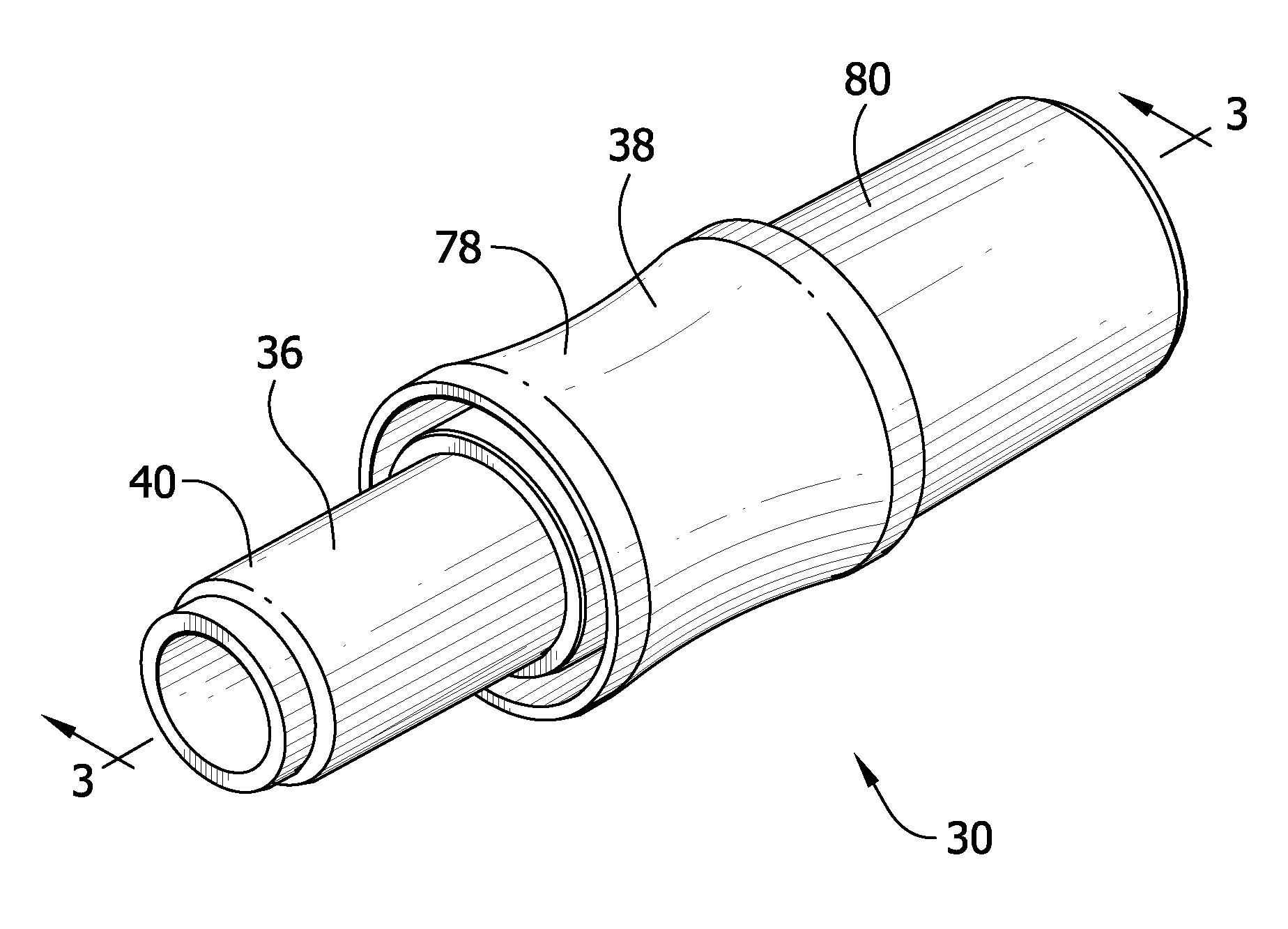
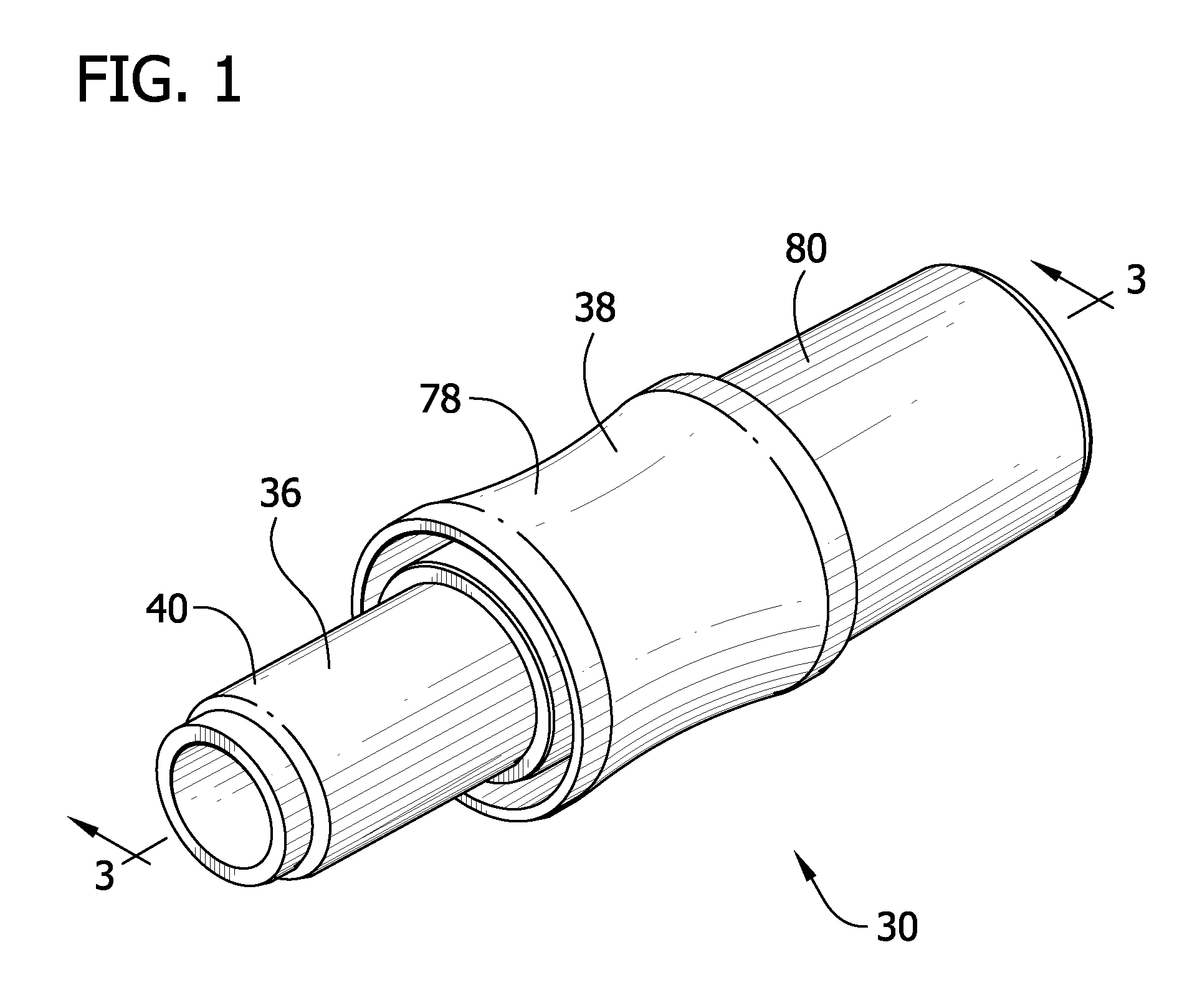
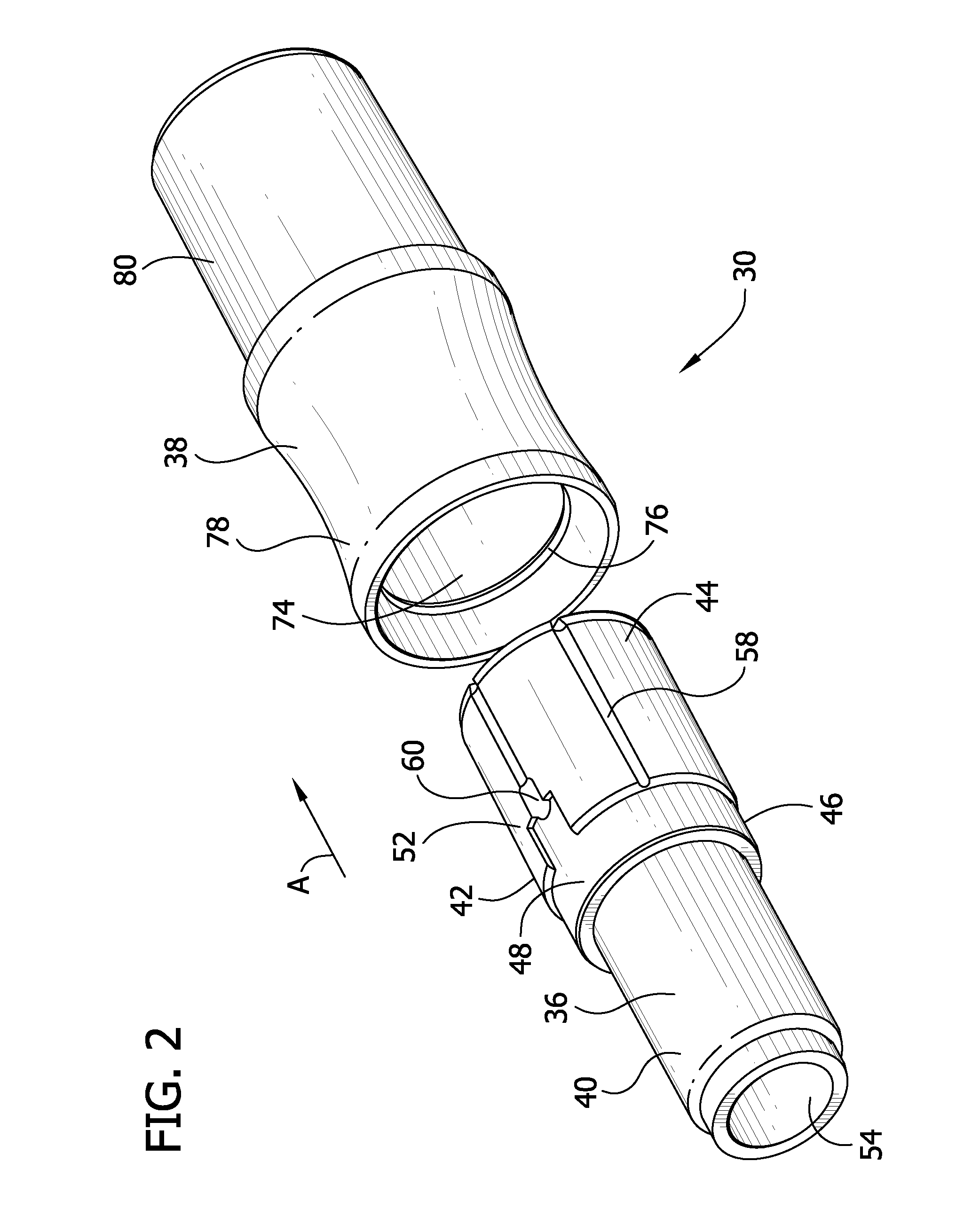
[0049]Referring now to the drawings, a connector assembly 30 constructed according to the principles of the present invention is shown in FIGS. 1 and 2 to comprise a first connector 36 and a second connector 38. As described more fully hereinafter, the first and second connectors 36, 38 are capable of discriminating connection to preferentially achieve fluid-tight connection of the connectors, and avoid fluid-tight connection with non-complying connectors. The connector system 30 may be used, for example, to connect a controller 2 to a compression therapy device 1 for cyclically supplying air pressure to a bladder 4 of the device (see, FIGS. 32 and 33). The compression therapy device 1 illustrated in FIG. 32 is of the type which is applied to the foot for repeatedly compressing the foot to force blood out of the foot and discourage pooling of blood in the foot that can lead to clots. Although a foot compression therapy device 1 is illustrated, other types of compression therapy devi...


PUM


Abstract

A connector assembly includes first and second mating connectors that can be joined to make a fluid connection. The connectors are constructed to discriminate improper connectors so that no fluid tight connection can be formed with improper connectors. The connector assembly can be used with a system for compression therapy to prevent deep vein thrombosis.

Description

CROSS-REFERENCE TO RELATED APPLICATIONS[0001]This application is a continuation-in-part of U.S. application Ser. No. 11 / 533,924, filed Sep. 21, 2006, the contents of which are incorporated herein by reference.TECHNICAL FIELD[0002]The present disclosure relates to safety connectors for use in medical applications, particularly for use with compression therapy devices. The present disclosure also relates to discriminating safety connector assemblies and, more particularly, to a discriminating safety connector assembly for fluidly coupling at least two lumens capable of forming a non-leaking fluid circuit.BACKGROUND OF THE INVENTION[0003]In a medical environment, many devices have tubing adapted for manual connection in order to provide a fluid connection between devices or between a device and a patient including enteral feeding pumps and intravenous feeding lines. Each of these devices includes one or more connectors that a user or practitioner may inadvertently connect together. Thi...

Claims


Application Information

Patent Timeline
Patent Type & Authority Applications(United States)
IPC IPC(8): A61B17/00
CPCA61H9/0078Y10T403/70A61M39/10A61M39/1011A61M2039/1027A61M2039/1094A61M2205/6045F16B7/0413F16B7/0426F16B9/02F16L2201/20A61B17/135F16L25/00Y10T403/30A61H2205/12Y10T137/9029
Inventor HANLON, JAMES G.SWISHER, DAVID R.
Owner KPR U S LLC
Why Eureka
Try Eureka