
Decoder, signal processing system, and decoding method

Inactive Publication Date: 2008-03-27
PANASONIC CORP
View PDF12 Cites 8 Cited by
  • Summary
  • Abstract
  • Description
  • Claims
  • Application Information

AI Technical Summary

Benefits of technology

[0013] In view of the above-described problems, the present invention has been achieved. An object of the present invention is to provide a decoder (e.g., audio codec) in which, when encoded data including two kinds of data, i.e., first code data appearing every several frames and second code data certainly appearing every frame, is decoded, continuation of a period of time in which decoding cannot be performed is prevented even if first code data used in decoding is not obtained.
[0014] To achieve the object, an embodiment of the present invention is a decoder for decoding encoded data having a structure including two kinds of data, i.e., first code data appearing every time every several frames and second code data certainly appearing every frame, and arranged to be decode

Problems solved by technology

In the digital broadcasting or communications system employing the AAC+SBR method, an event may occur in which a frame is not received or is inappropriately received (called frame loss).
When a frame is lost in this manner, original data cannot be normally decoded.
However, when a period of time in which decoding cannot be normally performed continues, the accuracy of estimation is deteriorated, thereby making it difficult to obtain a desired effect.
For example, when sbr_header information is not inserted for a long period of time (e.g. one minute), decoding of the SBR method cannot be normally performed for as long as one minute.

Method used


Image

  • Decoder, signal processing system, and decoding method
  • Decoder, signal processing system, and decoding method

Examples


Embodiment Construction

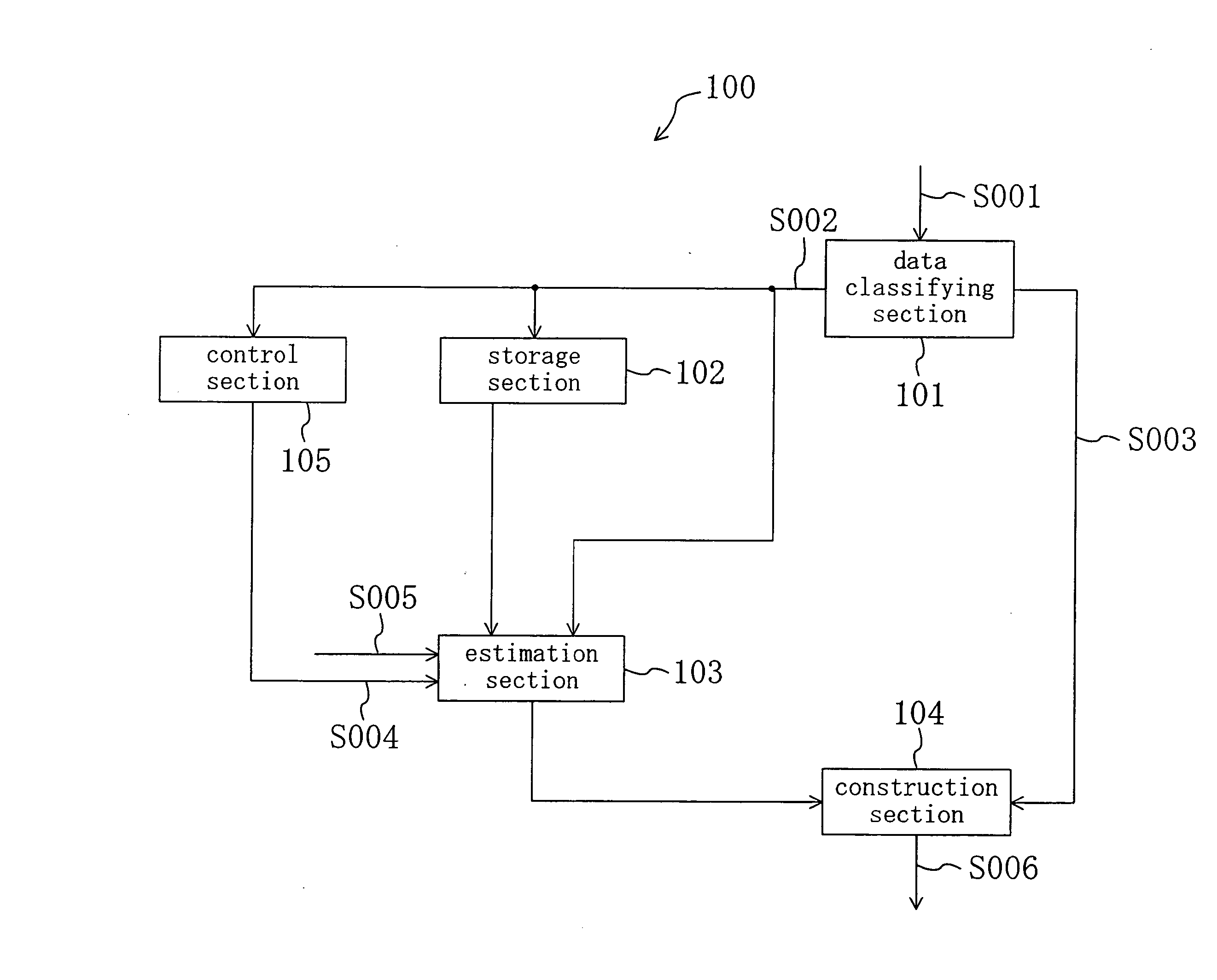
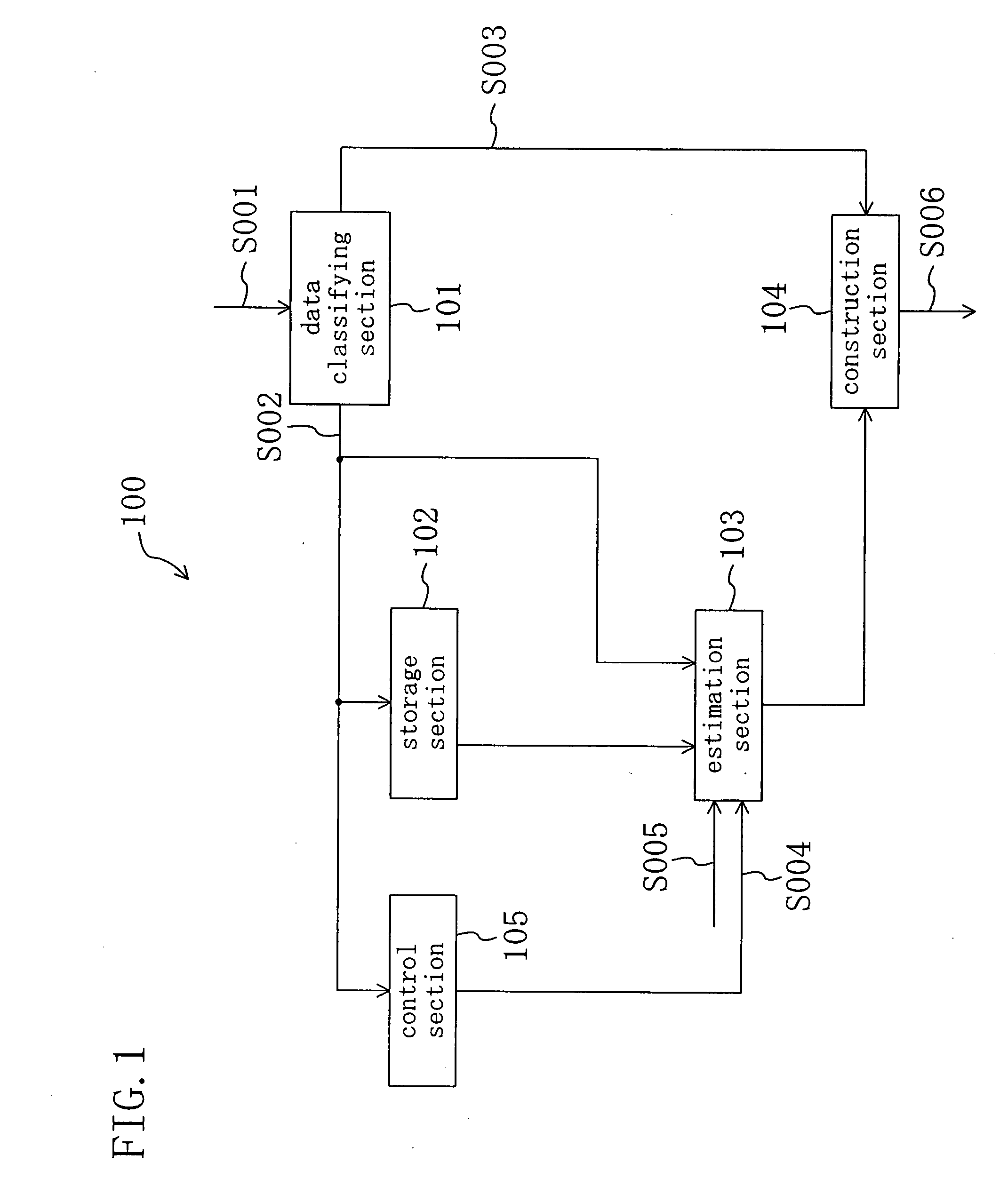
[0016]FIG. 1 is a block diagram showing a configuration of a decoder 100 according to an embodiment of the present invention. The decoder 100 is an exemplary device for decoding audio data (audio data S001) encoded by the SBR method and outputting the resultant data. The decoder 100 can be combined with an output unit (e.g., an amplifier, and may further include a loudspeaker) or the like so as to construct a signal processing system (e.g., an audio player). Note that audio data encoded by the SBR method includes first code data appearing every several frames (sbr_header information) and second code data certainly appearing every frame.

[0017] [Configuration of Decoder 100]

[0018] As shown in FIG. 1, the decoder 100 comprises a data classifying section 101, a storage section 102, an estimation section 103, a construction section 104, and a control section 105.

[0019] The data classifying section 101 classifies and outputs audio data S001 into first code data S002 and second code data...


PUM


Abstract

A storage section is provided for storing a plurality of pieces of first code data. Further, an estimation section is provided for, when first code data used in decoding exists in a current frame to be decoded or the storage section, outputting the first code data, and when not, estimating first code data corresponding to the current frame to be decoded from one or more pieces of past or future first code data stored in the storage section and earlier or later than the current frame to be decoded, and outputting the estimated first code data.

Description

CROSS REFERENCE TO RELATED APPLICATIONS [0001] This Non-provisional application claims priority under 35 U.S.C. §119(a) on Patent Application No. 2006-257206 filed in Japan on Sep. 22, 2006, the entire contents of which are hereby incorporated by reference. BACKGROUND OF THE INVENTION [0002] 1. Field of the Invention [0003] The present invention relates to a decoder for decoding encoded data which includes two kinds of data, i.e., first code data appearing every several frames and second code data certainly appearing every frame, and is arranged to be decoded based on the two kinds of data. [0004] 2. Description of the Related Art [0005] Audio data or the like may be encoded, transferred, or recorded into a recording medium in units of a set of data within a predetermined period of time (referred to as a frame). [0006] For example, the AAC+SBR method is an encoding method which can transfer audio information ranging from a low band to a high band in a digital broadcasting or communi...

Claims


Application Information

Patent Timeline
IPC IPC(8): G10L19/00G10L19/005G10L19/02
CPCG10L19/005
Inventor TAKEYA, RINTAROMATSUMOTO, MICHIHIRO
Owner PANASONIC CORP
Learn More