Lighting method of microwave excitation discharge lamp

a discharge lamp and microwave technology, applied in the direction of electric variable regulation, process and machine control, instruments, etc., can solve the problems of unsuitable products, inability to yield uniform products, and inability to produce uniform products

Active Publication Date: 2012-04-24
ORC MFG
View PDF7 Cites 7 Cited by
  • Summary
  • Abstract
  • Description
  • Claims
  • Application Information

AI Technical Summary

Benefits of technology

[0026]The object of this invention is, solving the above-mentioned existing problems, to prevent continuation of abnormal state occurring immediately after the lighting start of an electrodeless discharge lamp ignited by a DC driven magnetron.
[0027]In order to solve the above-mentioned problem, the following method is employed in this invention. It is the lighting method of an electrodeless discharge lamp to drive the electrodeless discharge lamp in a resonator with a microwave generated by a magnetron supplied with high-voltage DC power converted from AC power. In this method, at a start period from beginning of supply of the high-voltage DC power until discharge stabilization of the electrodeless discharge lamp, the high-voltage DC power is supplied as increasing gradually and the supply of the high-voltage DC power is stopped repeatedly. At a stabilized period after discharge stabilization of the electrodeless discharge lamp, when an abnormal voltage of the high-voltage DC power is sensed, the supply of the high-voltage DC power to the magnetron is stopped momentarily.

Problems solved by technology

And also, UV radiation irradiation can raise the removability or adhesion.
Uniform products can hardly be yielded because of local fluctuation of UV radiation irradiation and high speed of the manufacturing line in case of using rippled power source in these high-speed processes.
Then inequality of irradiation on products is caused and uniform products are not available.
On the other hand, there is also a fault that abnormal oscillation tends to occur.
An abnormal state may occur suddenly even if magnetron drive power is stable and a discharge lamp is also at steady state when ripple-free DC power is applied.
When sudden abnormal operation arises in a magnetron, the magnetron does not return to the normal state of stable operation because an anode voltage does not reach zero since DC power is supplied.
This is not a desirable state for a magnetron and a discharge lamp.
And, a magnetron heats up itself by reflective waves and it damages if the luminescence medium in the microwave excitation electrodeless discharge lamp evaporates inadequately right after the lighting start.

Method used


Image

  • Lighting method of microwave excitation discharge lamp
  • Lighting method of microwave excitation discharge lamp
  • Lighting method of microwave excitation discharge lamp

Examples


embodiment

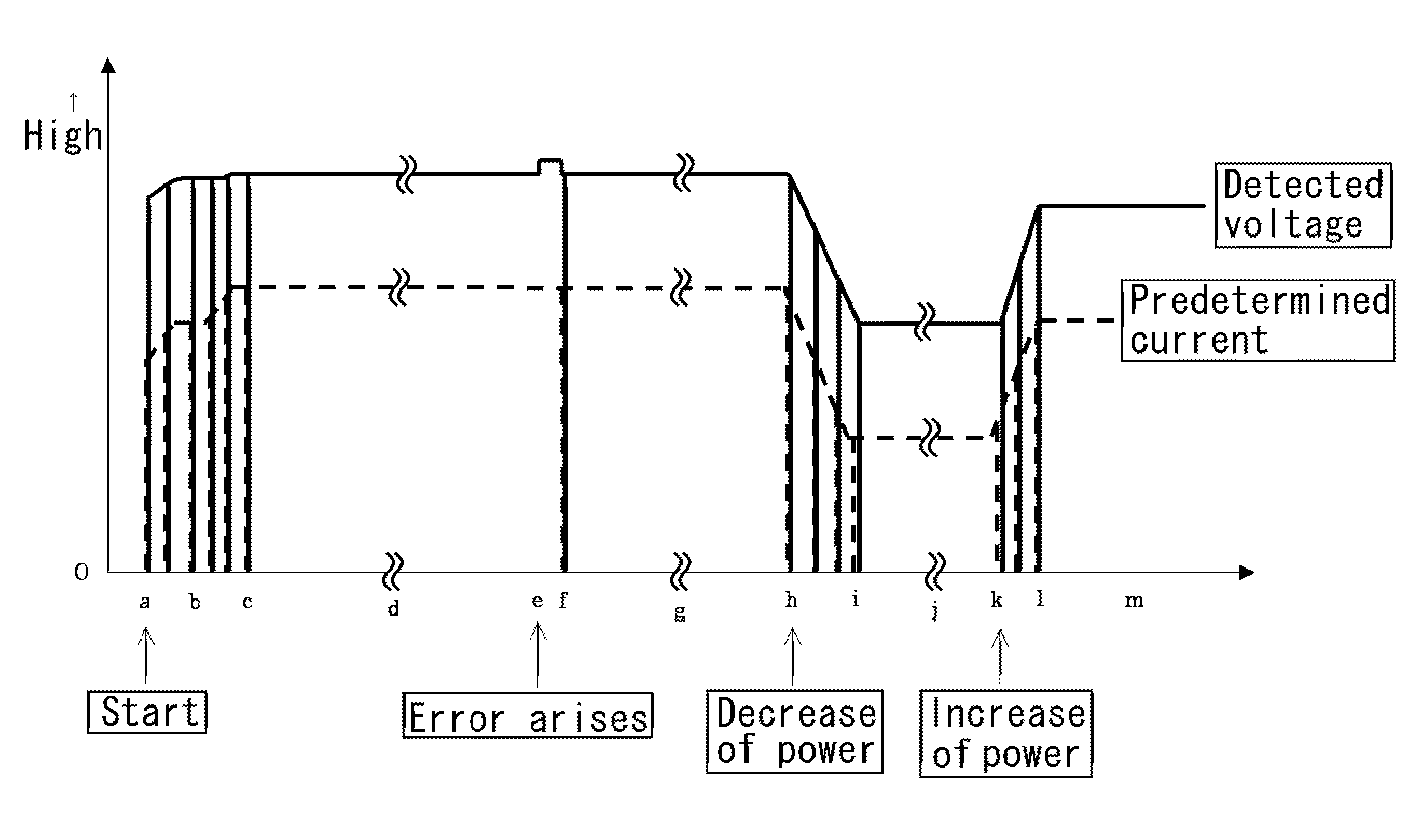
[0031]The embodiment of this invention is a method of lighting an electrodeless discharge lamp in the way to increase high-voltage DC power supply gradually at the start period, to stop momentarily high-voltage DC power supply repeatedly, and to stop momentarily high-voltage DC power supply to the magnetron when an abnormal voltage of high-voltage DC power is detected at a stable discharging period.

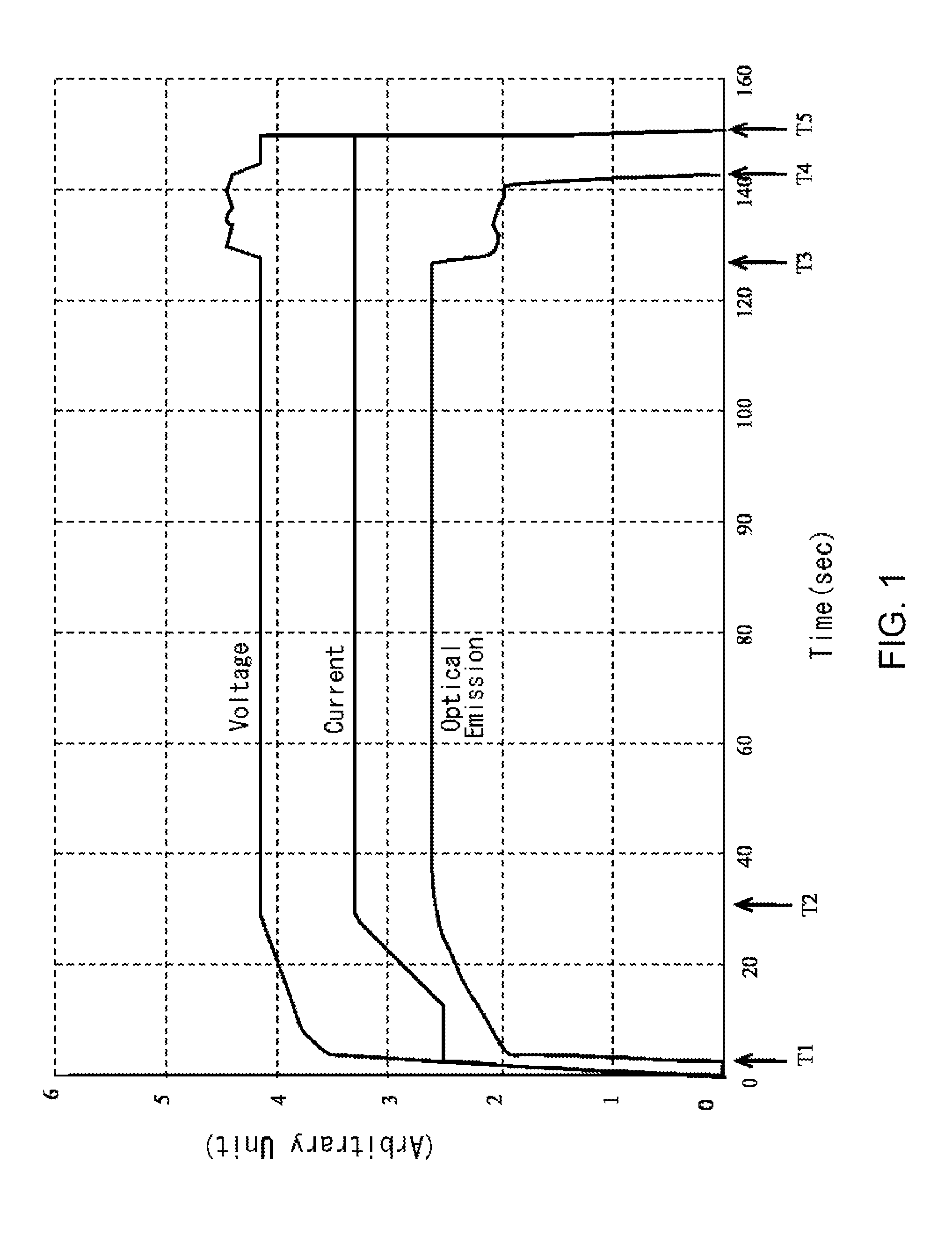
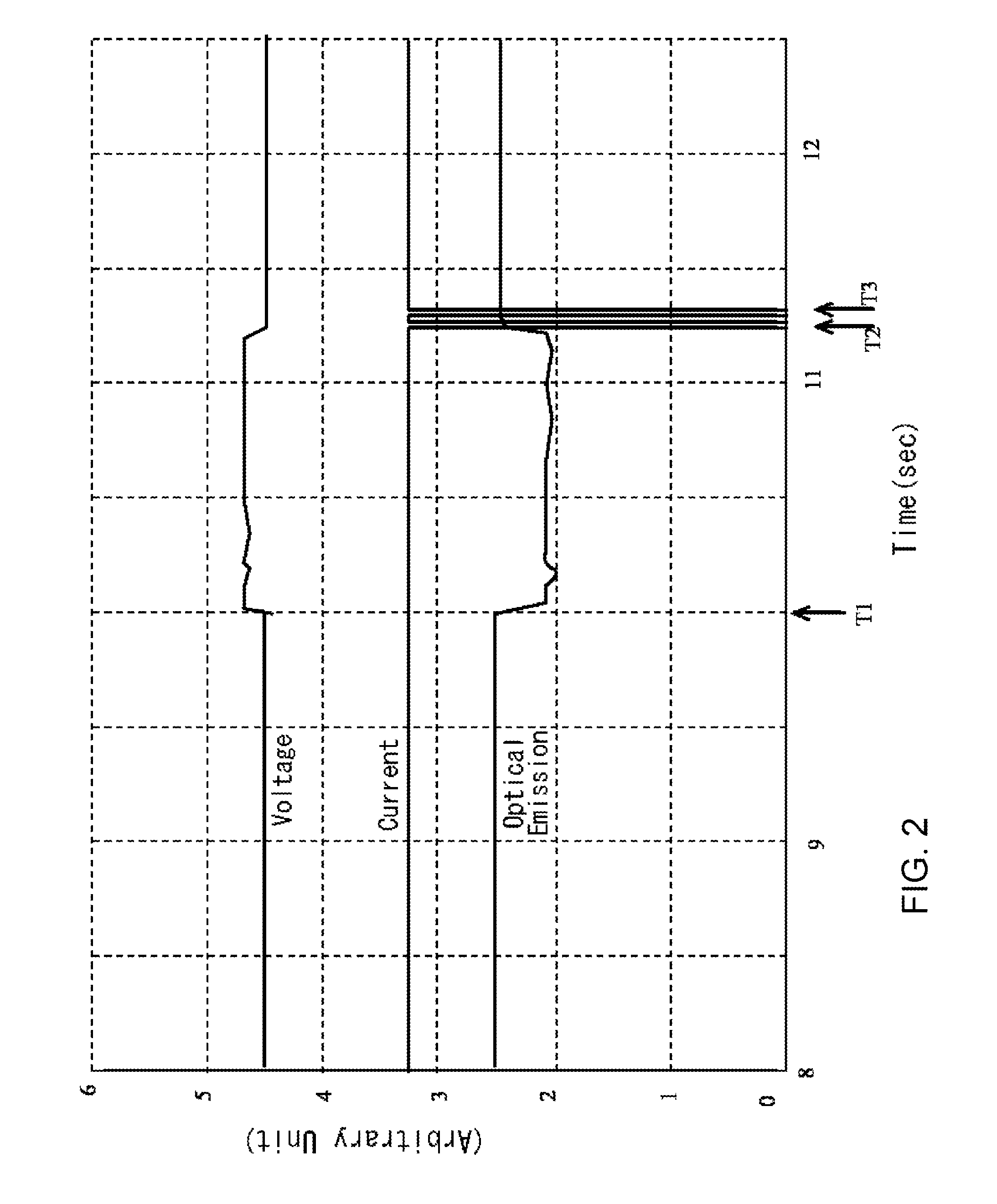
[0032]FIG. 1 is the time chart of the lamp puncturing experiment for checking the method of lighting an electrodeless discharge lamp in the embodiment of this invention. FIG. 2 is the time chart of an effect check experiment of the method of lighting electrodeless discharge lamp. FIG. 3 is a diagram of a magnetron operation mode.

[0033]FIG. 4 is a functional block diagram of the lighting equipment to employ the method of lighting electrodeless discharge lamp in the embodiment of this invention. In FIG. 4, the utility power 1 is AC power in 50 Hz or 60 Hz. A rectifier 2 is a means to change...


PUM


Abstract

To prevent the continuation of the abnormal state occurring immediately after the lighting start of the electrodeless discharge lamp excited by a DC driven magnetron and to recover promptly from the abnormal state at the steady state period. Lighting start of an electrodeless discharge lamp is performed in soft start mode. Increasing the power supply to the magnetron gradually, the lamp is turned into a lighting state for longer time than the time for the luminescence medium to evaporate fully absorbing microwave. At that period, the output of DC power supply is periodically cut off momentarily, resetting the abnormal state. Then, stable DC power is supplied. At the steady state period, the anode current of the magnetron is controlled to be constant. When rise of the operation voltage of the magnetron is detected, the output of DC power supply is cut off momentary to recover to the steady state.

Description

FIELD OF INVENTION[0001]The present invention relates to a method of lighting a microwave excitation discharge lamp, especially to a method of lighting an electrodeless discharge lamp to emit high-power UV radiation with applying almost ripple-free DC power.BACKGROUND OF THE INVENTION[0002]An electrodeless discharge lamp does not need electrodes in the lamp bulb as it is ignited with applying a microwave out of a magnetron. Therefore, its operation life is long because of no decay of electrodes, no contamination of enclosed gas and no contamination of lamp envelope of quartz glass or so. The focus of the electrodeless discharge lamp is smaller than an electroded discharge lamp because of its small inner diameter. The electrodeless discharge lamp should be held in an adequate microwave cavity resonator and the magnetron microwave should be applied through an adequate waveguide (guide tube or coaxial cable) to the lamp with an antenna situated in the cavity resonator in order to apply...

Claims


Application Information

Patent Timeline
Patent Type & Authority Patents(United States)
IPC IPC(8): H01J1/02
CPCH05B41/24H01J65/044H01J65/04H05B6/68H05B41/288
Inventor SHINOGI, AKIRA
Owner ORC MFG
Why Eureka
Try Eureka