

Test device for tubular specimens
- Summary
- Abstract
- Description
- Claims
- Application Information
AI Technical Summary
Benefits of technology
Problems solved by technology
Method used
Image

Examples
Embodiment Construction
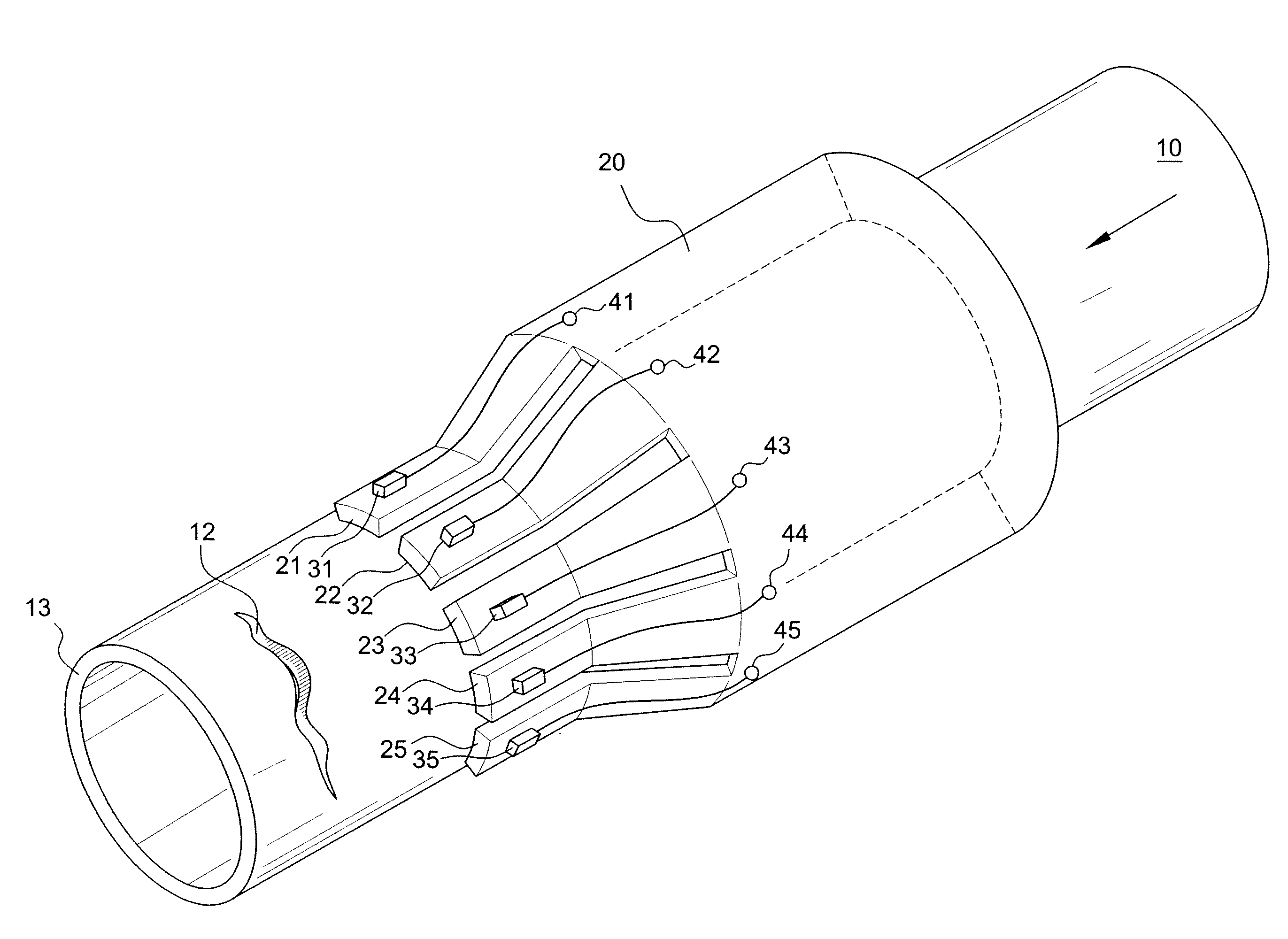
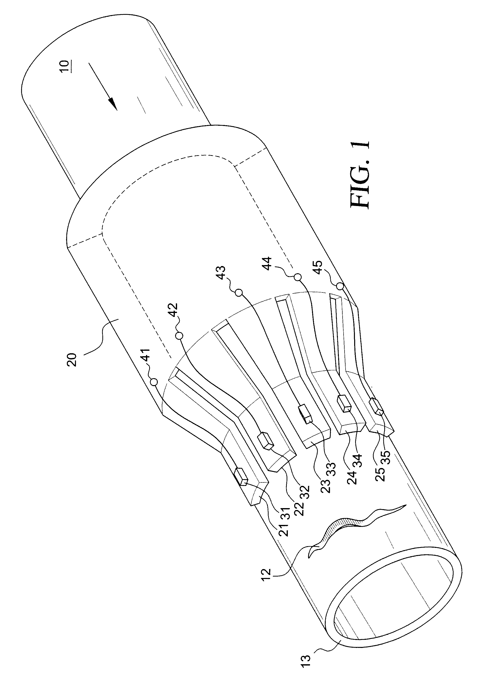
[0012]FIG. 1 shows a sensor carrier 20 which is slotted and shaped by bending such that a number (for example, 4 to 8), finger-shaped sensor holding devices 21-25 are provided. The finger-shaped sensor holding devices 21-25 are formed such that the sensor holding devices have elastic pretensioning and allow the attached sensors 53 for detection of magnetic stray flux quantities to rest elastically on the specimens. Furthermore, the forming is such that the sensor holding devices 21-25 are located on an imaginary cylindrical surface around the specimen, as shown in the figure.
[0013]In accordance with the invention, a number (normally 2, 3, 4, or 8) of individual sensor carriers 20 is mounted on a holding device so that the sensor carriers surround the entire pipe periphery. According to one embodiment of the invention, the sensor carrier 20 is suited to being shaped by bending around its lengthwise axis such that it can be inserted into holding devices which are made of different siz...
PUM
 Abstract
Description
Claims
Application Information