Adaptive intelligent electronic horn

a technology of intelligent electronic horns and horns, applied in the field of electronic horns, can solve the problems of mechanical soniferous apparatuses that cannot be operated in fully harmony resonance, frequent oscillation, and inability to fully harmony the resonance of mechanical soniferous apparatus, and achieve the effect of wide range pulse width and increased sensors

Inactive Publication Date: 2008-12-18
ZHAO HONGWEI
View PDF2 Cites 11 Cited by
  • Summary
  • Abstract
  • Description
  • Claims
  • Application Information

AI Technical Summary

Benefits of technology

[0012]Said thermally controlled on-off ratio adjusting circuit (108A) is used to control a pulse width of an oscillation signal from the oscillating circuit (102) based on a voltage of power supply and / or an ambient temperature.
[0013]Said voltage controlled on-off ratio adjusting circuit (108B) is used to control a pulse width of an oscillation signal from the oscillating circuit (102) based on a voltage of power supply and / or an ambient temperature.
[0014]When the ambient temperature is lowered, the thermally controlled on-off ratio adjusting circuit (108A) generates narrow pulse widths; conversely, when raised, the same generates wide range pulse width.
[0015]In the present invention, with increased sensors and on-off ratio adjusting circuit (108), oscillation frequency of oscillation signals from the oscillating circuit (102) is in resonance the oscillation occurs at a specific frequency of the mechanical soniferous apparatus (112) not affected by ambient environment changing or voltage power source alterations. The mechanical soniferous apparatus (112) outputs max voice voltage with harmony resonances.

Problems solved by technology

But lowering the temperature may frequent the oscillation.
It leads to a mechanical problem that the mechanical soniferous apparatus (112) or the like could not be operated within thoroughly harmony resonance.
Besides, the voltage fed into the electronic horn changed also detrimentally affects the actual output voice voltage.

Method used


Image

  • Adaptive intelligent electronic horn
  • Adaptive intelligent electronic horn
  • Adaptive intelligent electronic horn

Examples


Embodiment Construction

[0019]The description is described in detail according to the appended drawings hereinafter.

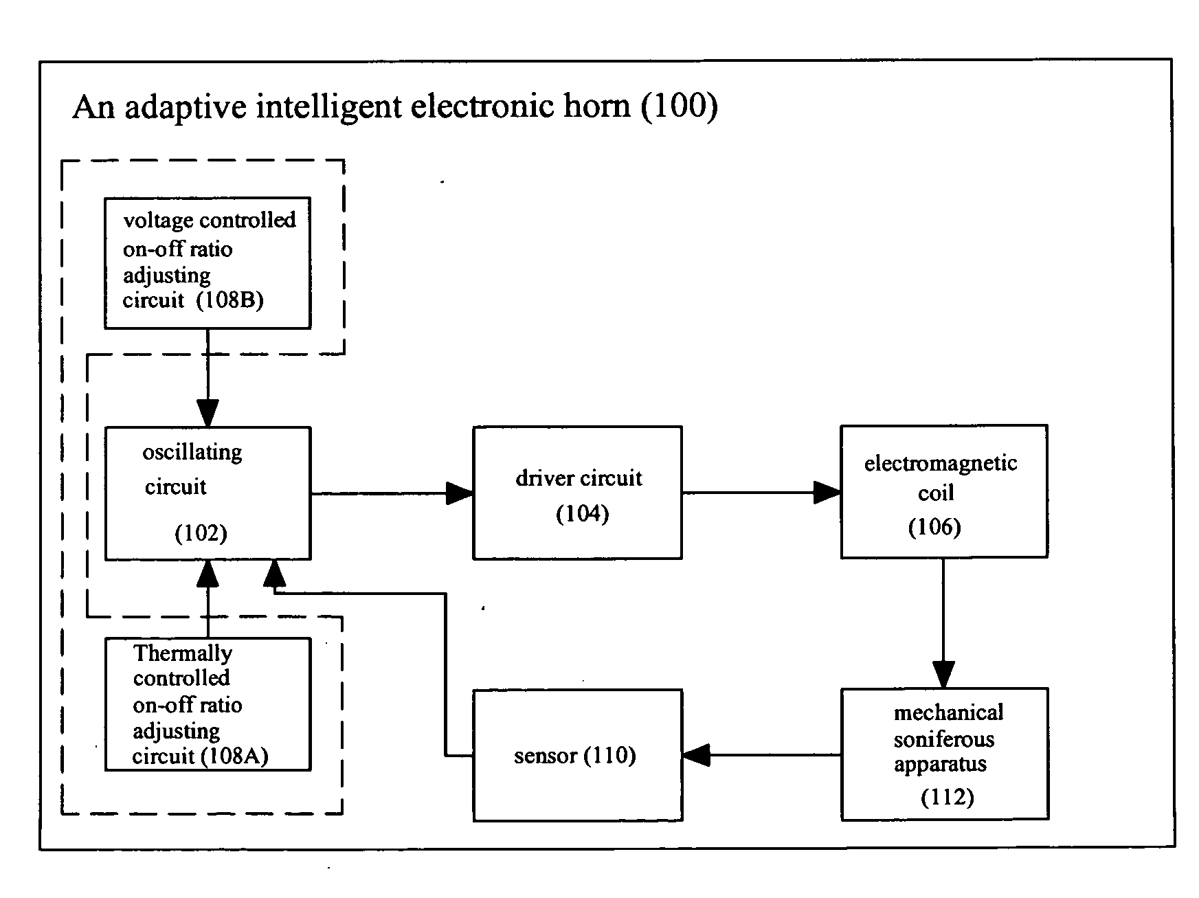
[0020]In the present invention, with pulse width and oscillation frequency of oscillation signals from an oscillating circuit, a mechanical soniferous apparatus (112) oscillates under harmony resonance outputs max voice voltage.

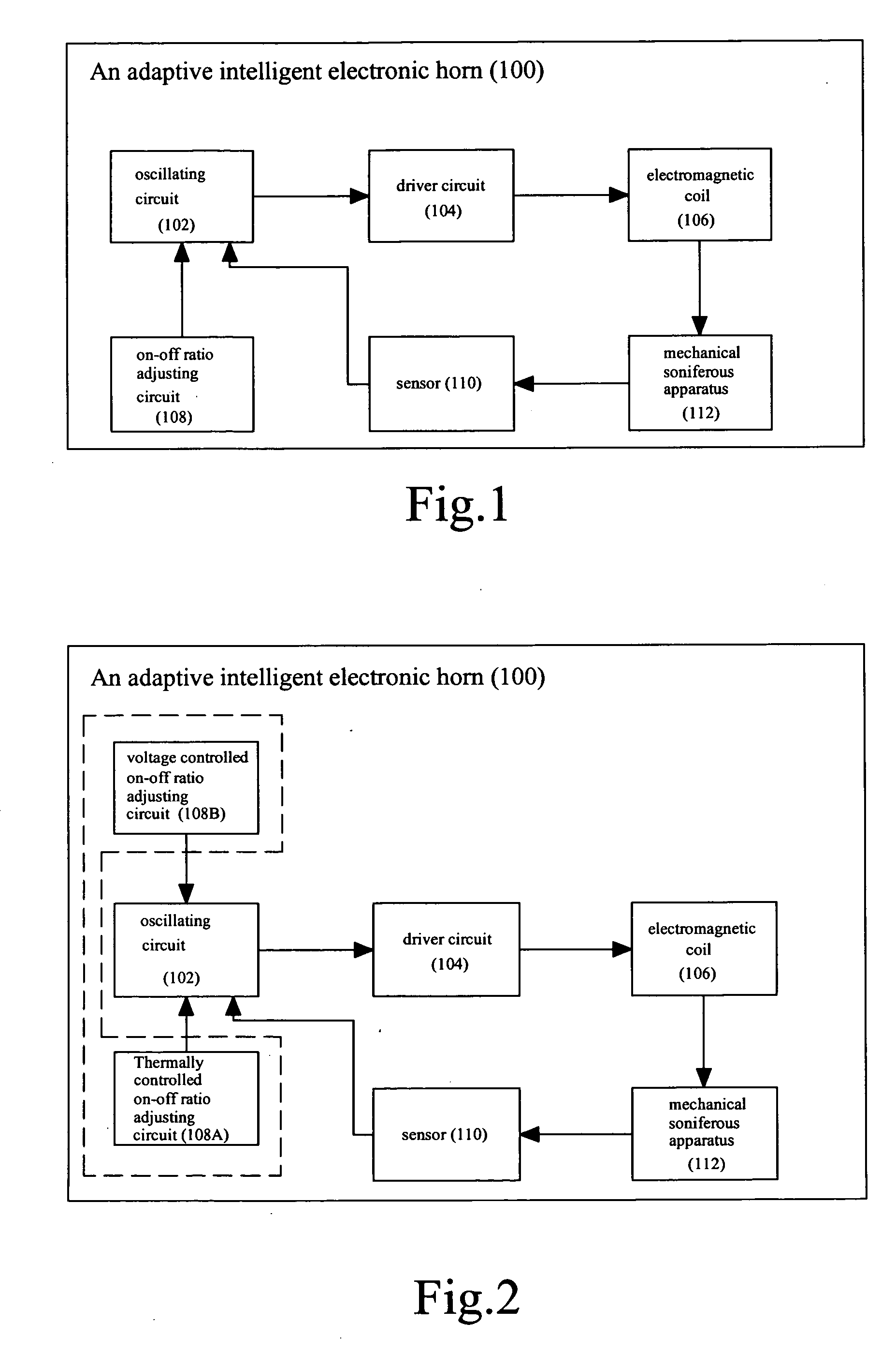
[0021]As shown in FIG. 1, an adaptive intelligent electronic horn (100) includes said mechanical soniferous apparatus (112), an electromagnetic coil (106), a driver circuit (104), and said oscillating circuit; a sensor (110) is provided between said mechanical soniferous apparatus (112) and said oscillating circuit; an on-off ratio adjusting circuit (108) is provided at an input end of the oscillating circuit.

[0022]The sensor (110) is used to measure the oscillation frequency of the mechanical ratio adjusting circuit and feedback the measured oscillation frequency signal to the oscillating circuit.

[0023]Said sensor (110) can be selected from a sound sensor, a oscillati...


PUM


Abstract

An adaptive intelligent electronic horn (100) comprises a mechanical soniferous apparatus (112), an electromagnetic coil (106), a driver circuit (104) and an oscillating circuit (102). A sensor (110) is provided between the mechanical soniferous apparatus (112) and the oscillating circuit (102). An on-off ratio adjusting circuit (108) is provided at the input end of the oscillating circuit (102). The sensor (110) measures the oscillation frequency of the mechanical soniferous apparatus (112) and feedbacks the measured oscillation frequency signal to the oscillating circuit (102). The on-off ratio adjusting circuit (108) controls a pulse width of an oscillation signal from the oscillating circuit (102) based on a voltage of power supply and/or an ambient temperature. The oscillating circuit (102) outputs corresponding oscillation signal to the driver circuit (104) based on the oscillation frequency signal received from the sensor (110) and/or the control signal from the on-off ratio adjusting circuit (108).

Description

FIELD OF THE INVENTION[0001]The present invention is related to an electronic horn; particularly, to an adaptive intelligent electronic horn (100) changes volume according to a changing circumstance, and takes advantage of the surroundings as part of the horn.BACKGROUND OF THE INVENTION[0002]Usually, an electronic horn reached required sound levels are driven by an electronic switch to determine whether an electromagnetic coil (106) disposed inside the horn is open or closed. Then, at least, movements of a larger flat diaphragm (i.e. mechanical soniferous apparatus (112)) instead of the actual horn ducting may help resonate the sound.[0003]Under such circumstance, the electromagnetic coil (106) driven by the electronic switch to be open or closed at a fixed on-off ratio. However, oscillation frequency of the mechanical soniferous apparatus (112) or the like is subject to variations due to ambient environment changing. Such as ambient temperature around the mechanical soniferous appa...

Claims


Application Information

Patent Timeline
Patent Type & Authority Applications(United States)
IPC IPC(8): G08B3/10
CPCB06B1/0215B06B2201/53G10K9/13
Inventor ZHAO, HONGWEI
Owner ZHAO HONGWEI
Why Eureka
Try Eureka