Method for calibrating a time-of-flight system and time-of-flight system

a technology of time-of-flight and time-of-flight, which is applied in the direction of wave based measurement systems, instruments, etc., can solve the problems of reducing the accuracy of distance measurement, and achieve the effect of reducing the impact of contamination

Pending Publication Date: 2020-08-27
AMS AG
View PDF5 Cites 7 Cited by
  • Summary
  • Abstract
  • Description
  • Claims
  • Application Information

AI Technical Summary

Benefits of technology

[0050]By using a short VCSEL pulse coupled with a histogram, the system can reduce the impact of contamination such as smudges on the cover and enable the ToF sensor to measure an accurate distance even when translucent coating is present. There are several methods for accomplishing this including ignoring the initial bins of the histogram and recording the initial peak indicating a crosstalk response of the histogram then subtracting the respective difference values from the ongoing values. Furthermore, calibration may involve dynamically compensating for the addition or subtraction of translucent coating from the cover plate. In c...

Problems solved by technology

In previous systems, translucent coating de...

Method used


Image

  • Method for calibrating a time-of-flight system and time-of-flight system
  • Method for calibrating a time-of-flight system and time-of-flight system
  • Method for calibrating a time-of-flight system and time-of-flight system

Examples


Embodiment Construction

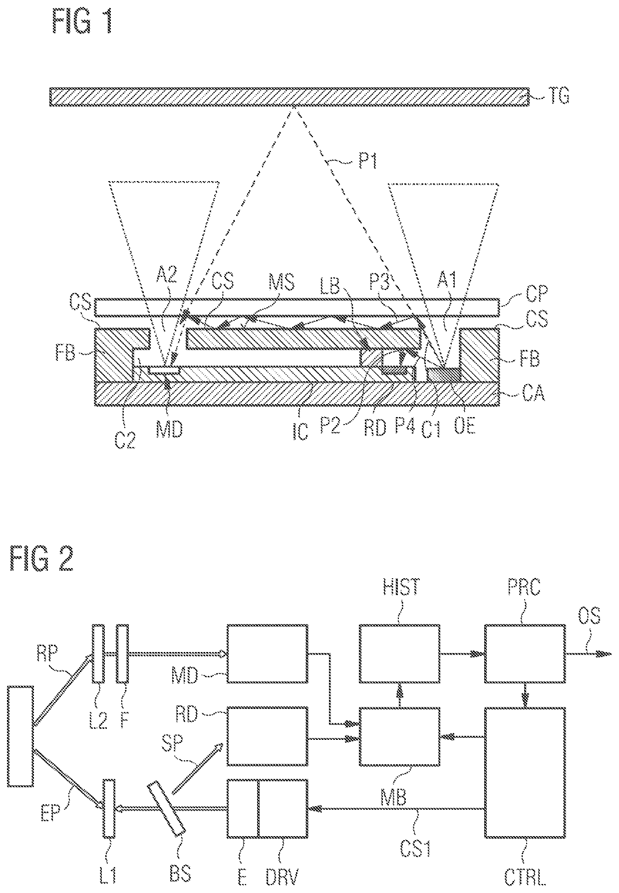
[0060]FIG. 1 shows an example implementation of a time-of-flight sensor behind a cover according to the improved concept. For example, the drawing shows a side view of the time-of-flight sensor implemented as an optical sensor module, e.g. as part of a time-of-flight system. The module comprises a carrier CA and an opaque housing arranged on the carrier. The housing comprises a light barrier LB which divides the housing into a first and a second chamber C1, C2. The first and second chambers C1, C2 are further confined laterally by a frame body FB which is arranged in the housing. A cover section CS is located opposite to the carrier CA and thereby covers the chambers C1, C2. The cover section CS has a main surface MS which essentially is parallel to a main surface of the carrier CA.

[0061]The cover section CS, frame body FB, and light barrier LB may be manufactured by a continuous piece of material, such as a mold material, for example. The carrier CA provides mechanical support and ...


PUM


Abstract

A method is presented for calibrating a time-of-flight system having a time-of-flight sensor located behind a cover plate. The method involves emitting a plurality of sending pulses of light in response to respective trigger pulses of a control signal and detecting received pulses of light. Respective difference values are determined which are representative of a time period between one of the sending pulses and one of the received pulses. The difference values are accumulated into a number of bins of at least one histogram. The method further involves recording at least one crosstalk response in the histogram within a predetermined range of bins, and calibrating the histogram using the recorded crosstalk response. Finally, an output signal is generated which is indicative of a time-of-flight based on an evaluation of the calibrated histogram.

Description

CROSS-REFERENCE TO RELATED APPLICATIONS[0001]The present application is the national stage entry of International Patent Application No. PCT / EP2018 / 075608, filed on Sep. 21, 2017, which claims the benefit of priority of European Patent Application No. 17198595.5, filed on Oct. 26, 2017 and U.S. Provisional Application No. 62 / 562,307 filed on Sep. 22, 2017, all of which are hereby incorporated by reference in their entirety for all purposes.FIELD OF THE INVENTION[0002]The invention relates to the field of calibrating a time-of-flight system.BACKGROUND OF THE INVENTION[0003]Time-of-flight sensors have many applications related to distance measurement, including proximity detection, assisting the autofocusing of digital cameras, multi-zone autofocus, gesture detection or 3D camera applications, for example. A time-of-flight, ToF, can be determined by emitting pulses of electromagnetic radiation and detecting the reflections from an object. This technique can utilize multiple pulses ove...

Claims


Application Information

Patent Timeline
IPC IPC(8): G01S7/497G01S7/487
CPCG01S7/4876G01S7/497G01S7/4813G01S2007/4975
Inventor GLOVER, KERRYLUEGER, MANFREDKAPPEL, ROBERTMAUTNER, CHRISTIANMANNINGER, MARIO
Owner AMS AG
Why Eureka
Try Eureka