Pulsed light generation method

a technology of pulse energy and light, applied in the direction of lasers, semiconductor lasers, manufacturing tools, etc., can solve the problems of the risk of deteriorating beam quality, and the limited pulse energy that determines the efficiency of laser processing, so as to increase the pulse peak, avoid appearance, and increase the core diameter of optical fibers

Inactive Publication Date: 2012-12-06
MEGAOPTO
View PDF2 Cites 7 Cited by
  • Summary
  • Abstract
  • Description
  • Claims
  • Application Information

AI Technical Summary

Benefits of technology

[0008]The present invention has been developed to eliminate the problems described above. It is an object of the present invention to provide a method of enabling generation of pulsed lights each having a narrow pulse width and high effective pulse energy
[0010]The pulsed light generation method according to the present invention makes the single semiconductor laser output the plurality of pulsed lights separated from each other by a predetermined pulse width, for each period given according to the predetermined repetition frequency. In this manner, by outputting the plurality of pulsed lights within a primary pulse generation period, the present invention is superior in a point that resistance characteristics to stimulated Raman scattering (SRS) and stimulated Brillouin scattering (SBS) can be improved, and a point that a heat reserve in a laser processing can be reduced. On the other hand, Patent Documents 2 and 3 are different from the present invention in that the inventions of these documents output only one pulse for each period given according to a repetition frequency. The invention of Patent Document 4 obtains a plurality of pulsed lights in one period given according to a repetition frequency, by multiplexing the plurality of pulsed lights from the plurality of different pulse light sources at different times. However, Patent Document 4 is different from the present invention in that each pulse light source of this document outputs only one pulse in one period given according to a repetition frequency.

Problems solved by technology

In order to avoid appearance of a nonlinear effect, the core diameter of the optical fiber may be increased, however, in this case, there is a risk of deteriorating the beam quality.
On the other hand, it is preferable to compress a pulse width, so that pulse energy that determines the efficiency of laser processing and optical damage is limited.

Method used


Image

  • Pulsed light generation method
  • Pulsed light generation method
  • Pulsed light generation method

Examples


Embodiment Construction

[0026]In the following, a best mode for carrying out the present invention is described in detail with reference to the accompanying drawings. In the description of the drawing, elements identical to each other are denoted with the same reference numerals, and overlapping description is omitted.

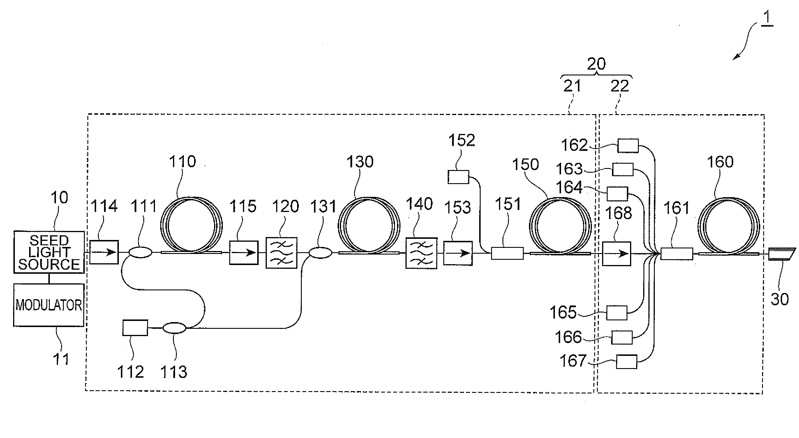
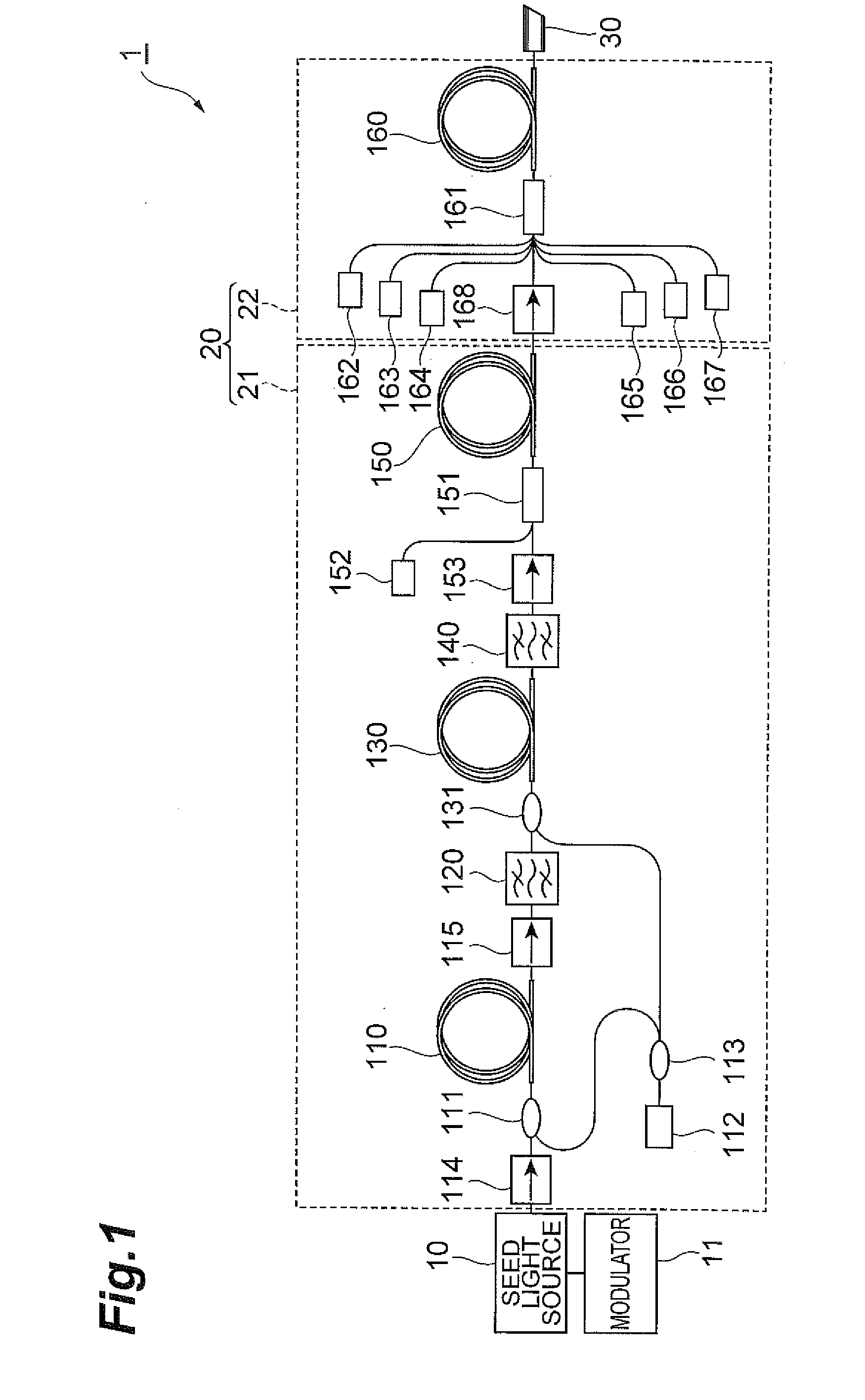
[0027]FIG. 1 is a view showing a configuration of an embodiment of a pulse light source (laser light source) for carrying out a pulsed light generation method according to the present invention. In FIG. 1, the pulse light source 1 has a MOPA (Master Oscillator Power Amplifier) structure, and comprises a seed light source 10 directly modulated by a modulator 11 and an optical fiber amplifier 20. The seed light source 10 includes a 1060 nm-band Fabry-Perot semiconductor laser that is directly pulse-modulated in a drive current range of 0 to 220 mA so as to realize a high repetition frequency of from 100 kHz to upper limit of 1 MHz or 10 MHz and a constant pulse width without depending on the re...


PUM

PropertyMeasurementUnit
repetition frequencyaaaaaaaaaa

Abstract

The present invention relates to a method of enabling generation of pulsed lights each having a narrow pulse width and high effective pulse energys. A pulse light source has a MOPA structure, and comprises a single semiconductor laser, a bandpass filter and an optical fiber amplifier. The single semiconductor laser outputs two or more pulsed lights separated by a predetermined interval, for each period given according to a predetermined repetition frequency. The bandpass filter attenuates one of the shorter wavelength side and the longer wavelength side, in the wavelength band of input pulsed lights.

Description

CROSS-REFERENCE TO RELATED APPLICATION[0001]This application is based upon and claims the benefit of priorities from U.S. Provisional Application No. 61 / 506,922, filed on Jul. 12, 2011 and Japanese Patent Application No. 2011-125584, filed on Jun. 3, 2011, the entire contents of which are incorporated herein by reference.BACKGROUND OF THE INVENTION[0002]1. Field of the Invention[0003]The present invention relates to a pulsed light generation method.[0004]2. Related Background Art[0005]A pulse light source is used for industrial purposes represented by laser processing, or the like. Generally, in laser processing of a fine target to be processed, to control constantly the pulse width of pulsed laser light is important for managing the processing quality including a thermal influence on the surroundings. Light outputted from an optical fiber laser light source, including an amplifying optical fiber that has a core doped with a rare earth element as an amplifying medium, has diffractio...

Claims


Application Information

Patent Timeline
Patent Type & Authority Applications(United States)
IPC IPC(8): H01S5/062
CPCB23K26/063B23K26/0656H01S3/06758H01S3/09415H01S3/10038H01S3/1618H01S3/176H01S3/0057H01S3/0064H01S3/0078H01S3/10046H01S3/1693H01S5/06216B23K26/0622B23K26/066
Inventor KAKUI, MOTOKITAMAOKI, SHINOBU
Owner MEGAOPTO
Why Eureka
Try Eureka