Ultra-wide band imaging method and device with enhanced focusing

An ultra-broadband imaging and focus enhancement technology, applied in measurement devices, radio wave reflection/re-radiation, utilization of re-radiation, etc., can solve the problems of strong equipment interference, slow target positioning, and complicated electromagnetic compatibility design.

Active Publication Date: 2013-06-26
山东山科感测智慧科技有限公司
View PDF4 Cites 7 Cited by
  • Summary
  • Abstract
  • Description
  • Claims
  • Application Information

AI Technical Summary

Problems solved by technology

Existing equipment transmits a signal with a wider pulse and a longer wavelength. Although the penetration is good, the detection accuracy is low; the existing equipment transmits a signal with a long cycle, slow detection and imaging, and is not suitable for fast-moving objects; the existing equipment requires high-voltage power supply. Reaching dozens or even hundreds of volts, the power consumption is large, and the power supply has strong interference with the equipment; the existing equipment adopts the traditional imaging algorithm, the target positioning is slow, and the accuracy is low; the existing equipment has low circuit integration and large volume, which is not conducive to portability; Most of the existing equipment receivers use high-frequency microwave devices, the electromagnetic compatibility design is complicated, the cost is high, and the noise immunity is poor

Method used


Image

  • Ultra-wide band imaging method and device with enhanced focusing
  • Ultra-wide band imaging method and device with enhanced focusing
  • Ultra-wide band imaging method and device with enhanced focusing

Examples


Embodiment Construction

[0114] The present invention will be further described below in conjunction with the drawings and embodiments.

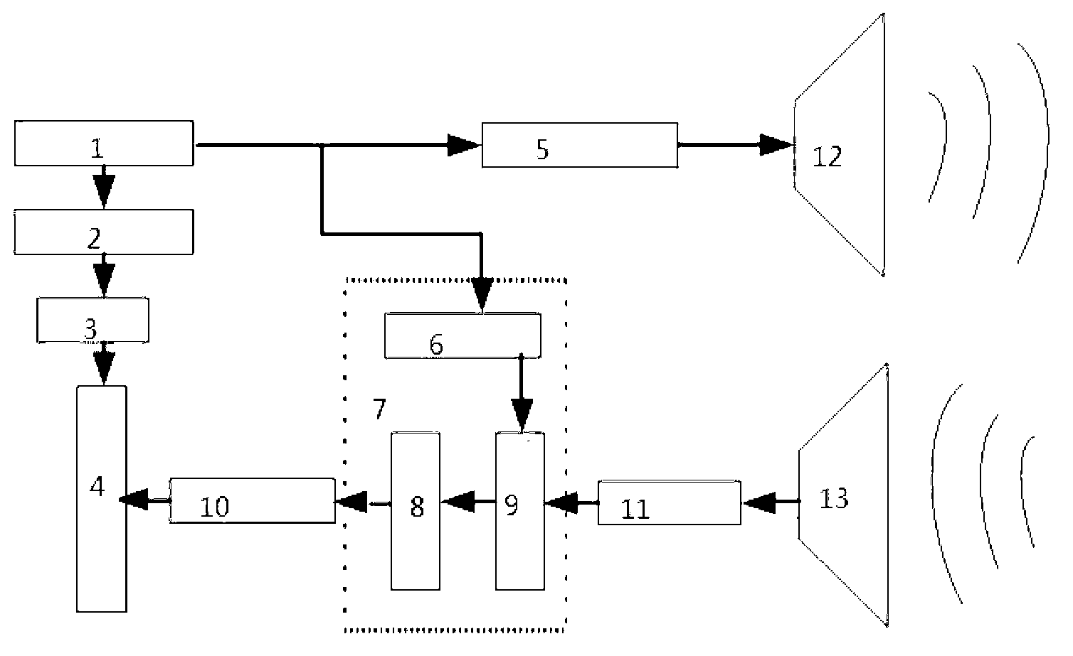
[0115] Such as figure 1 , The controller FPGA1 (Field Programmable Gate Array) controls the time domain signal transmitter 5 to send out a narrow pulse signal with a width of nanoseconds and a higher bandwidth spectrum. The narrow pulse signal is radiated by the transmitting antenna array 12 to detect the target. The receiving antenna array 13 sends the received weak reflection signal to the LNA (low noise amplifier 11), the signal is amplified and then enters the receiver 7. The receiver 7 parses the received high-speed weak signal into a digital signal, and collects data through multiple channels The unit 10 is fed into the signal processing and imaging module 4. At the same time, the controller FPGA1 controls the inertial positioning sensor 2 to measure the acceleration of the antenna device in real time, the data acquisition unit 3 sends the measurement result to...


PUM


Abstract

The invention discloses an ultra-wide band imaging method and device with enhanced focusing. A controller FPGA (filed programmable gate array) 1 controls a time domain transmitter to transmits a narrow pulse signal with nanosecond width and high band-width frequency spectrum. The narrow pulse signal is radiated by a transmitting antenna array 12 to probe a target. A receiving antenna array transmits a received weak reflection signal to a noise amplifier 11, the amplified signal enters a receiver 7, the receiver 7 analyzes the received high-speed weak signal into a digital signal, and the digital signal is transmitted to a signal processing and imaging module 4 through a multi-channel data acquisition unit 10. In the mean time, the controller FPGA 1 controls an inertial positioning sensor 2 to measure acceleration of equipment in real time, a data acquisition unit 3 transmits the measuring result to the signal processing and imaging module 4, and the position of the target is analyzed through an imaging algorithm program.

Description

Technical field [0001] The invention relates to an imaging method and device, in particular to an ultra-wideband imaging method and device with enhanced focus. Background technique [0002] Ultra-wideband imaging instrument is a typical system that realizes the detection of concealed targets in non-transparent media barriers. It has the advantage of non-invasive detection. It can penetrate non-transparent media barriers such as walls and buildings, and detect hidden targets behind the barrier. Positioning, tracking and imaging. Due to its ultra-wideband and high-resolution features, ultra-wideband imaging instruments can obtain fine echo responses of complex targets, which is extremely beneficial for target recognition and target imaging. With the help of these excellent characteristics of ultra-wideband imaging equipment, it is possible to detect the location and movement of terrorist militants in hidden areas, and reduce the casualties of anti-terrorism personnel. In addition...

Claims


Application Information

Patent Timeline
Patent Type & Authority Applications(China)
IPC IPC(8): G01S13/89
Inventor 王丰贵杨秀蔚王忠民崔洪亮成巍杨传法
Owner 山东山科感测智慧科技有限公司
Why Eureka
Try Eureka