Acceleration sensor

a technology of acceleration sensor and heat sensing, which is applied in the direction of acceleration measurement in multiple dimensions, solid-state devices, instruments, etc., can solve the problems of high cost and complicated production process, and achieve the effect of reducing production costs and simplifying production process

Inactive Publication Date: 2008-10-16
ROHM CO LTD
View PDF21 Cites 9 Cited by
  • Summary
  • Abstract
  • Description
  • Claims
  • Application Information

AI Technical Summary

Benefits of technology

[0008]An object of the present invention is to provide a heat sensing type acceleration sensor which can simplify the production process and reduce the production costs.
[0011]In the production process of the conventional heat sensing type acceleration sensor, the steps of forming a recess on the substrate and installing a heater and the thermocouples on the recess are required. However, such steps are not required in the production process of this acceleration sensor. Therefore, the production process is simplified, and the acceleration sensor can be produced at a low cost.
[0013]It is preferable that the sensor chip is disposed above the heating chip. In such a configuration, the heat from the respective heating elements satisfactorily reaches the thermocouples, so that it is possible to realize reduction in heating value of the heating elements and / or improvement in sensitivity of the thermocouple elements.
[0015]In such a configuration, the bump is interposed between the heating chip and the sensor chip, whereby the distance between the heating chip and the sensor chip can be accurately maintained at a predetermined interval. Therefore, a change in the heat radiation state from the heating elements can be satisfactorily detected by the thermocouple elements, and the acceleration applied to the acceleration sensor can be satisfactorily detected.
[0017]In such a configuration, the bump to be interposed between the heating chip and the sensor chip is formed by connecting a heating chip side bump and a sensor chip side bump formed of a Au material with a connecting metal formed of a Sn material. The Sn material has a melting point lower than that of the Au material, so that the Sn material that is a material of the connecting metal is provided on the tip end of the heating chip side bump and / or the sensor chip side bump, and heated and fused while in abutment of the heating chip side bump and the sensor chip side bump each other, the heating chip side bump and the sensor chip side bump can be reliably connected to each other.
[0019]In such a configuration, the heating chip and the sensor chip are sealed by the resin package, so that the heat radiation state from the heating elements can be prevented from changing by influence from the outside of the resin package. Therefore, the change in the heat radiation state from the heating elements can be satisfactorily detected by the thermocouple elements. Accordingly, acceleration applied to the acceleration sensor can be satisfactorily detected.

Problems solved by technology

However, in the above-described heat sensing type acceleration sensor, it is necessary to form a recess on the surface of the substrate and to install a heater and four thermocouples on the recess, resulting in complicated production process and high cost.

Method used


Image

  • Acceleration sensor
  • Acceleration sensor
  • Acceleration sensor

Examples


Embodiment Construction

[0024]Hereinafter, an embodiment of the present invention will be described in detail with reference to the accompanying drawings.

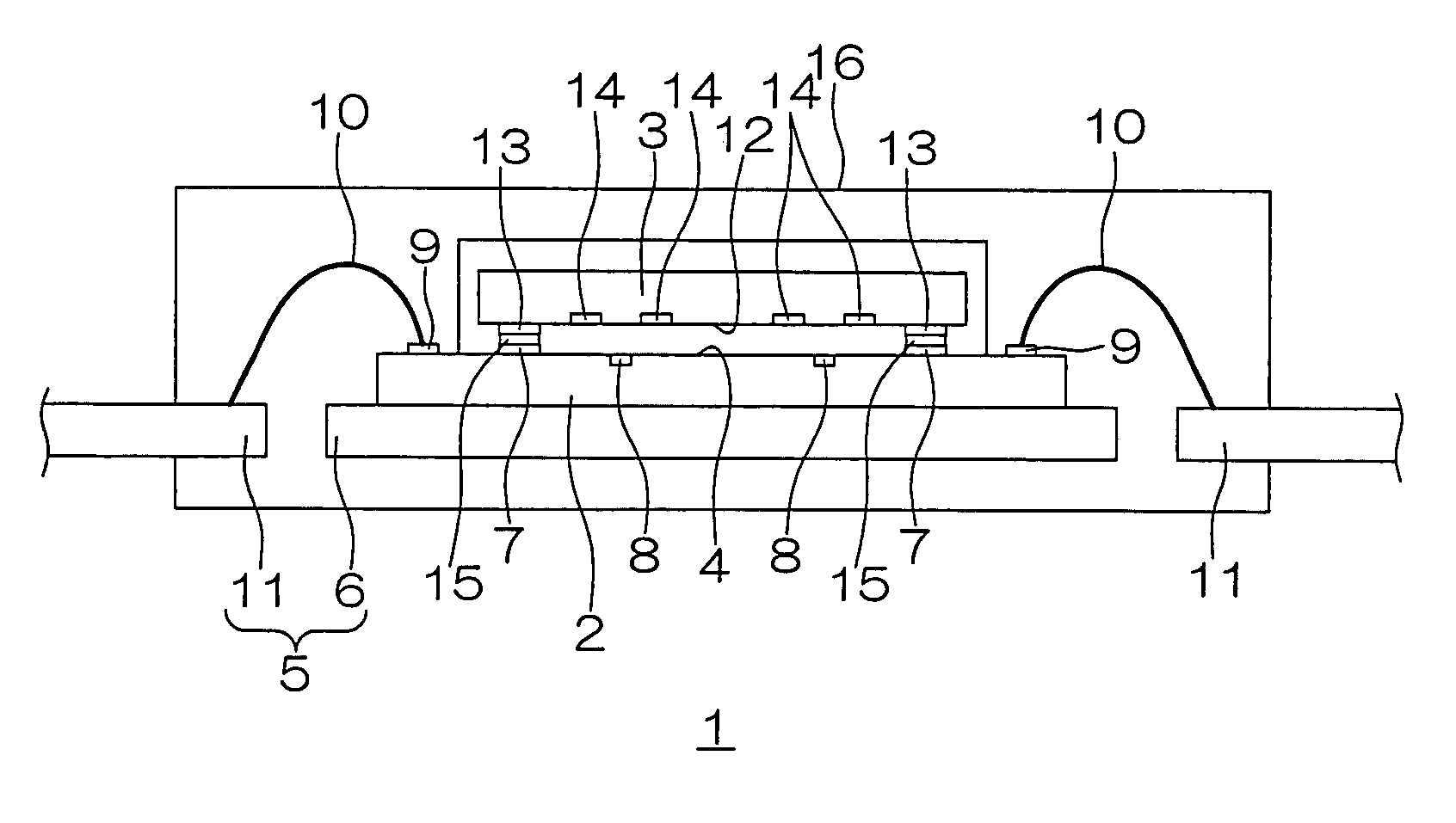
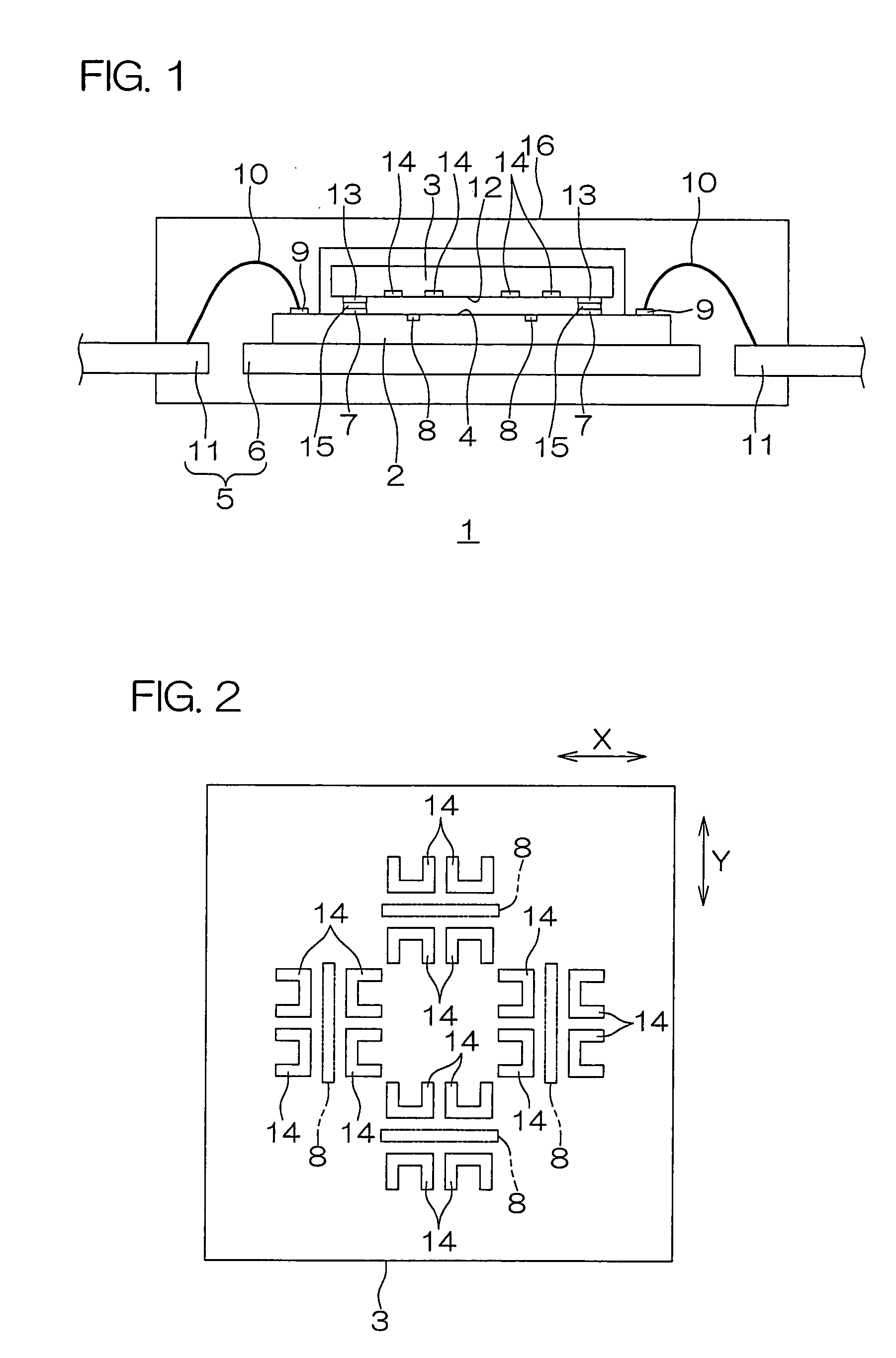
[0025]FIG. 1 is a schematic sectional view showing a construction of an acceleration sensor according to an embodiment of the present invention.

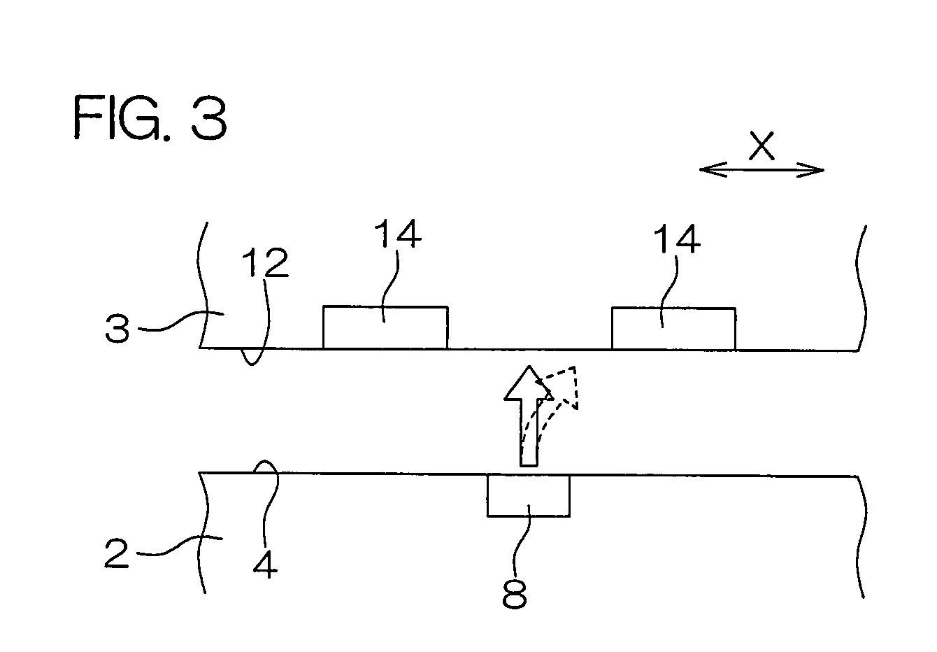
[0026]The acceleration sensor 1 is a heat sensing type acceleration sensor. This acceleration sensor 1 has a chip-on-chip structure in which a heating chip 2 and a sensor chip 3 are bonded to each other so that surfaces thereof face each other.

[0027]The heating chip 2 is formed into a substantially rectangular shape in a plan view. The heating chip 2 is die-bonded to an island 6 of a lead frame 5 in a face-up posture with the surface 4 thereof facing up. On the central portion of the surface 4 of the heating chip 2, a substantially rectangular chip bonding region is set to which the sensor chip 3 is bonded.

[0028]In the chip bonding region, a plurality of heating chip side bumps 7 are disposed at intervals along th...


PUM


Abstract

An acceleration sensor of the present invention is a heat sensing type acceleration sensor, and includes a heating chip formed with a heating element on a surface thereof, and a sensor chip formed with a thermocouple element on a surface thereof and disposed so that the surface faces the surface of the heating chip.

Description

BACKGROUND OF THE INVENTION[0001]1. Field of the Invention[0002]The present invention relates to a heat sensing type acceleration sensor.[0003]2. Description of Related Art[0004]Recently, MEMS (Micro Electro Mechanical Systems) have received increasing attention. The MEMS are microscopic electronic mechanical system parts / elements which are produced by means of semiconductor microfabrication techniques. As a typical MEMS, an acceleration sensor is known for detecting acceleration of an object.[0005]For example, a heat sensing type acceleration sensor includes a substrate having a recess on the surface thereof, four thermocouples installed on the recess, and a heater disposed at the center of the four thermocouples. Among the four thermocouples, two the thermocouples are disposed along the X axis at mutually opposite sides at equal intervals with respect to the heater, and the other two the thermocouples are disposed along the Y axis orthogonal to the X axis at mutually opposite side...

Claims


Application Information

Patent Timeline
Patent Type & Authority Applications(United States)
IPC IPC(8): G01P15/00
CPCG01P1/023G01P15/008G01P15/0802G01P15/18H01L2224/48091H01L2224/48247H01L2924/1461H01L2924/00014H01L2924/00H01L2924/181H01L2924/00012
Inventor NAKATANI, GORO
Owner ROHM CO LTD
Why Eureka
Try Eureka