
Control of engine torque reduction at upshift initiation

a technology of engine torque reduction and upshift initiation, which is applied in the direction of mechanical equipment, digital data processing details, instruments, etc., can solve the problems of poor shift quality, achieve less calibration effort, improve adaptability to different powertrains, and more consistent shift feel and energy dissipation

Active Publication Date: 2008-04-03
GM GLOBAL TECH OPERATIONS LLC
View PDF6 Cites 20 Cited by
  • Summary
  • Abstract
  • Description
  • Claims
  • Application Information

AI Technical Summary

Benefits of technology

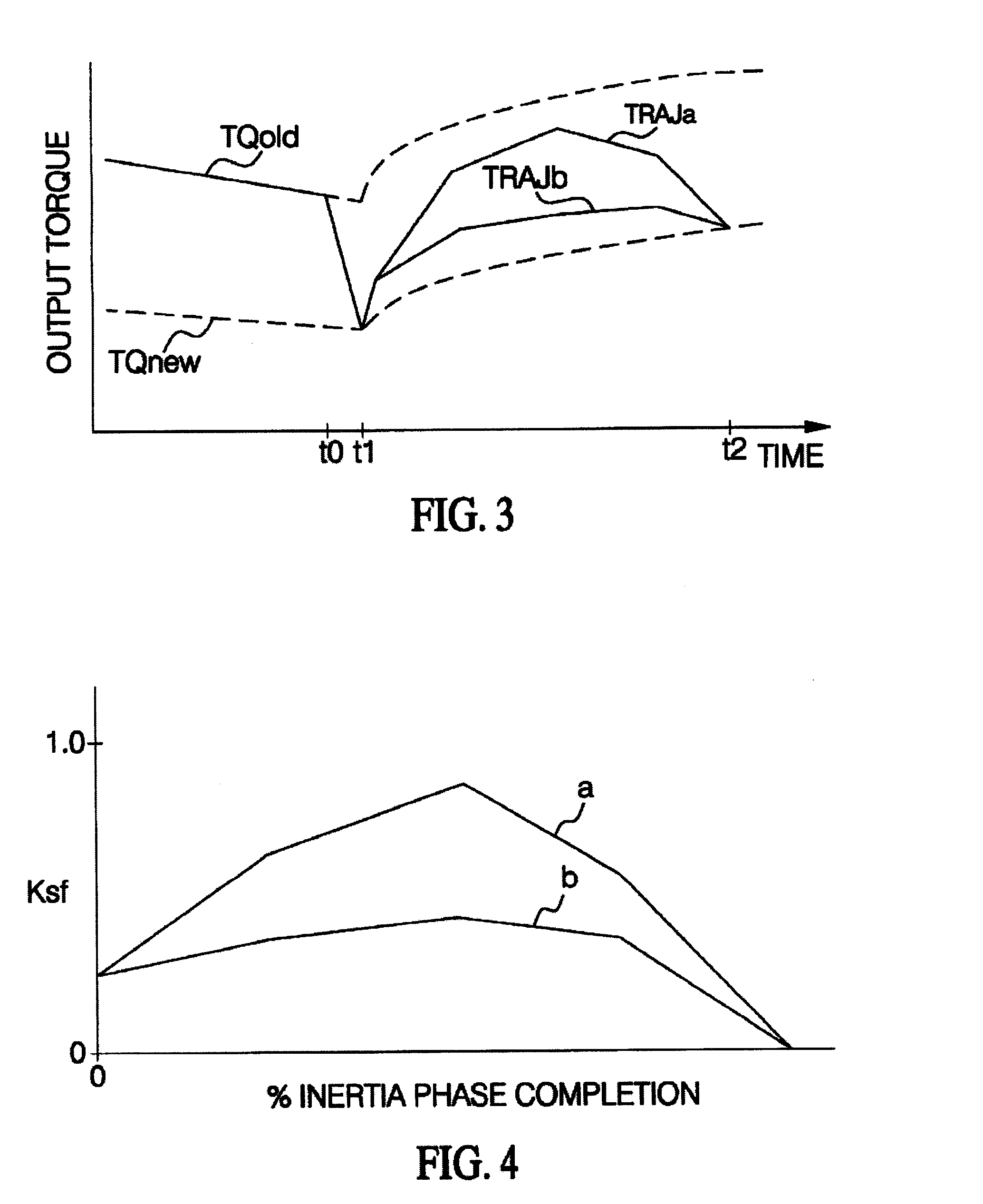
[0006]The present invention is directed to an improved control for an automatic transmission upshift, wherein the engine output torque and on-coming clutch pressure are coordinated during the shift based on an inverse dynamic model of the transmission to achieve a desired output torque trajectory. The desired output torque trajectory is influenced by operator demand, and an initial value of the desired output torque trajectory is used along with the engine output torque to develop an input acceleration trajectory. The inverse dynamic model of the transmission is used (1) to determine an engine output torque command that will achieve both the input acceleration trajectory and the desired output torque trajectory, and (2) to determine a feed-forward pressure command for the on-coming clutch that will produce the input acceleration trajectory, given the engine torque command. The desired output torque trajectory is used to determine the expected input speed, and a feed-back control term based on the deviation of the measured input speed from the expected input speed is used to adjust the on-coming clutch pressure command to account for model errors. Finally, the closed-loop feedback error is used to enable adaptive correction of the feed-forward control so that the feed-forward clutch pressure more nearly produces the commanded input shaft acceleration. Coordinating the on-coming pressure and engine output torque in this manner achieves more consistent shift feel and energy dissipation in the on-coming clutch, with less intensive calibration effort and improved adaptability to different powertrain and vehicle-type configurations. In the preferred embodiment, the engine torque reduction during shifting is accomplished by commanding engine output torque in a ramp-like or sloping fashion.

Problems solved by technology

Calibration engineers have deemed this result unacceptable, therefore, typical transmission calibrations require the on-coming clutch to gain capacity prior to the step torque reduction.
This method of operation also results in poor shift quality as a result of tie-up between the on-coming clutch and the off-going clutch prior to the engine torque reduction.

Method used


Image

  • Control of engine torque reduction at upshift initiation
  • Control of engine torque reduction at upshift initiation
  • Control of engine torque reduction at upshift initiation

Examples


Embodiment Construction

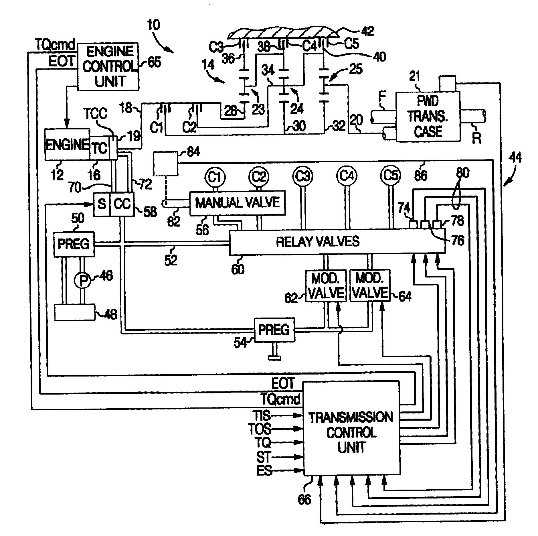
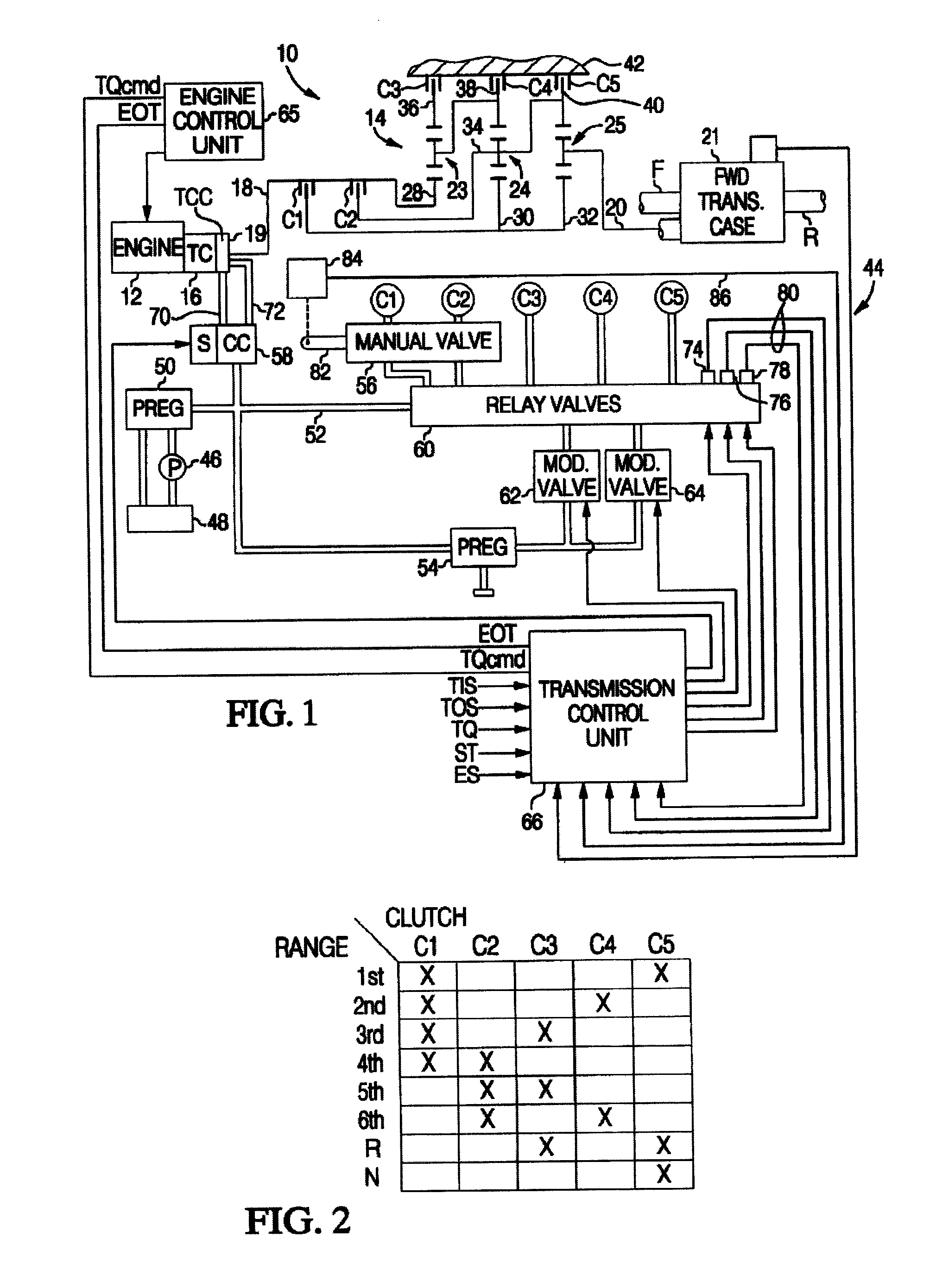
[0015]The control of this invention is described in the context of a multi-ratio power transmission having a planetary geartrain and electro-hydraulic control of a type known to those skilled in the art. Accordingly, the geartrain and control elements shown in FIG. 1 hereof have been simplified.

[0016]Referring to FIG. 1, the reference numeral 10 generally designates a vehicular powertrain having an engine 12, transmission 14, and a torque converter 16 providing a fluid coupling between engine 12 and a transmission input shaft 18. A torque converter clutch 19 is selectively engageable under certain conditions to provide a mechanical coupling between engine 12 and transmission input shaft 18. The transmission output shaft 20 may be coupled to the driving wheels of the vehicle in one of several ways. The illustrated embodiment of FIG. 1 depicts a four-wheel-drive (FWD) application in which the output shaft 20 is connected to a transfer case 21, which is also coupled to a rear drive sha...


PUM


Abstract

An improved control for an automatically shiftable transmission upshift, wherein the engine output torque and on-coming clutch pressure are coordinated during the shift based on an inverse dynamic model of the transmission to achieve a desired output torque trajectory. At the initiation of an upshift, the engine torque is commanded to decrease in a ramp-like or sloping fashion to and engine output torque value calculated using the dynamic model. This ramp-like or sloping decrease provides smooth shifting, while reducing the likelihood of tie-up between on-coming and off-going clutches within the automatically shiftable transmission.

Description

TECHNICAL FIELD[0001]This invention relates to a model-based upshift control for an automatic transmission, and more particularly to control of engine torque reduction at upshift initiation.BACKGROUND OF THE INVENTION[0002]In general, an automatically shiftable transmission for a motor vehicle includes a number of gear elements and selectively engageable friction elements (referred to herein as clutches) that are controlled to establish one of several forward speed ratios between an input shaft and output shaft of the transmission. The input shaft is coupled to a power source, such as an internal combustion engine through a fluid coupling, such as a torque converter, and the output shaft is coupled to the vehicle drive wheels through a differential gearset. Shifting from a currently established speed ratio to new speed ratio involves, in most cases, disengaging a clutch (off-going clutch) associated with the current speed ratio and engaging a clutch (on-coming clutch) associated wit...

Claims


Application Information

Patent Timeline
IPC IPC(8): B60W10/04
CPCB60W10/06B60W10/115B60W30/19F16H61/061F16H61/686Y10T477/677F16H2302/00F16H2306/30Y02T10/56Y10T477/6937Y10T477/675F16H63/502B60W2050/0031Y02T10/40
Inventor RUNDE, JEFFREY K.
Owner GM GLOBAL TECH OPERATIONS LLC
Learn More