Eureka AIR delivers breakthrough ideas for toughest innovation challenges, trusted by R&D personnel around the world.

Light emitting device with beam shaping structure and manufacturing method of the same

a technology of light emitting devices and beam shaping structures, which is applied in the manufacturing of semiconductor/solid-state devices, semiconductor devices, electrical devices, etc., can solve the problems of increasing manufacturing costs, occupying more overall space, and not being suitable for certain applications specifying projection light sources with a small viewing angle. , to achieve the effect of increasing manufacturing costs, occupying a large amount of overall space, and reducing the number of units

Active Publication Date: 2020-10-06
MAVEN OPTRONICS CO LTD
View PDF48 Cites 0 Cited by
  • Summary
  • Abstract
  • Description
  • Claims
  • Application Information

AI Technical Summary

Benefits of technology

[0010]In view of the above-explained deficiencies, an improved CSP LED device with a beam shaping structure is disclosed according to the present disclosure. The viewing angle or spatial radiation pattern can be adjusted to fit various applications without using an inefficient reflector, which will result in excessive optical energy dissipation because of the light trapped inside the CSP LED device structure. Another advantage of the CSP LED device is to maintain its small form factor using a streamlined fabrication process without high manufacturing cost.
[0011]One object according to some embodiments of the present disclosure is to provide a CSP LED device and a manufacturing method thereof. Through a proper 100 design of a Beam Shaping Structure (BSS), the viewing angle of the CSP LED device can be reduced ranging from about 120 degrees to about 140 degrees compared with a comparative five-surface emitting CSP LED device, whose viewing angle ranges from 140 degrees to 160 degrees, while maintaining substantially the same form factor. The CSP LED device can be fabricated using a relatively streamlined and less expensive manufacturing process. Through another embodiment of a BSS according to the present disclosure, the viewing angle of the CSP LED device can be increased to be larger than about 160 degrees compared with a comparative five-surface emitting CSP LED to fulfill the specifications of certain applications.
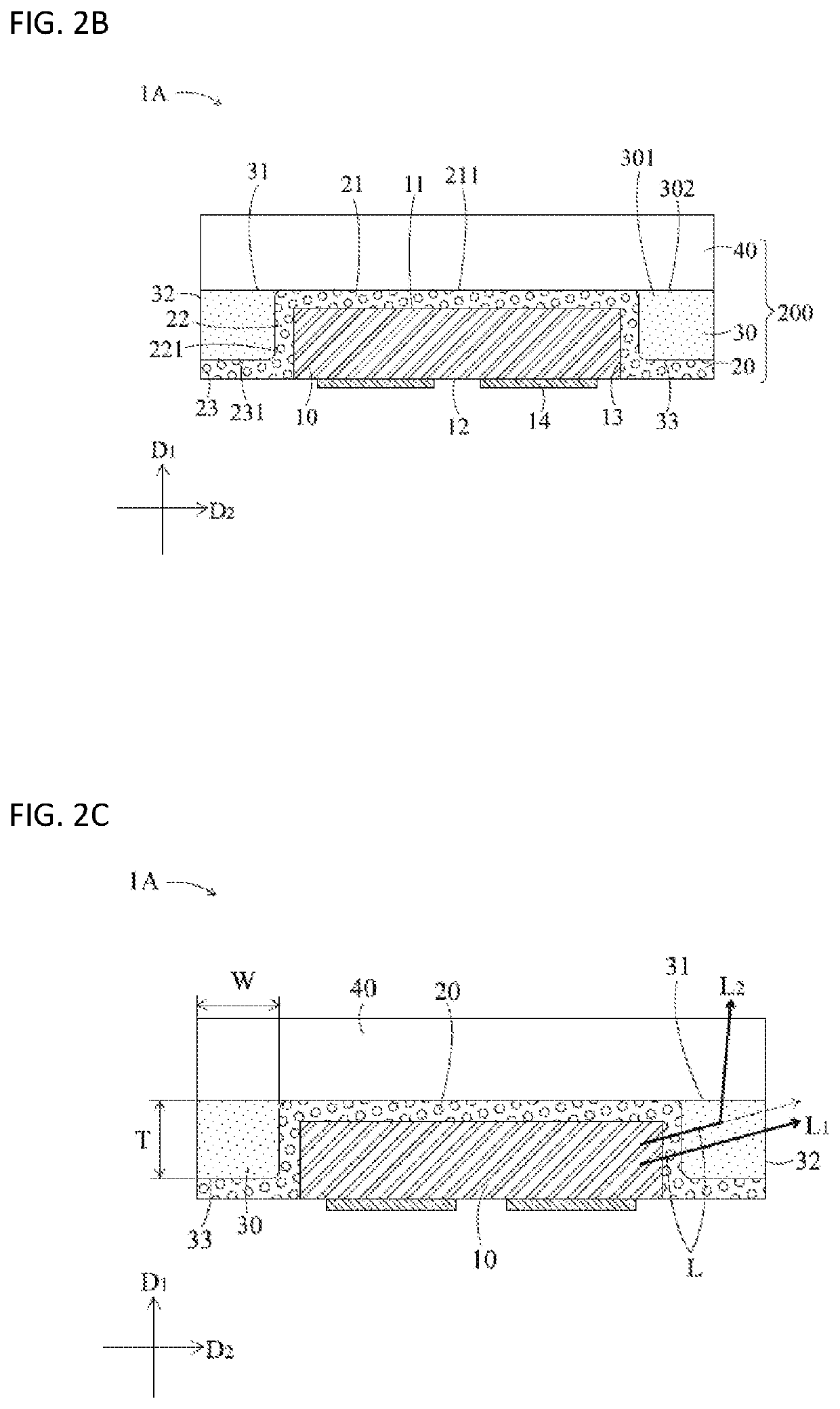
[0012]To achieve the aforementioned object, a smaller viewing angle CSP LED device according to some embodiments of the present disclosure comprises an LED semiconductor die, a photoluminescent structure, and a beam shaping structure. The LED semiconductor die is a flip-chip LED semiconductor die having an upper surface, a substantially in parallel but opposite lower surface, an edge surface and a set of electrodes. The photoluminescent structure is formed covering the upper surface and the edge surface of the LED semiconductor die, and the BSS is strategically disposed covering an edge portion of the photoluminescent structure. The BSS is fabricated with composition materials made of dispersing light scattering particles inside a polymer resin material with a relatively low concentration of the light scattering particles, such as equal to or less than about 30 wt. %, equal to or less than about 20 wt. %, or equal to or less than about 10 wt. %. Thus, a portion of the light emitted from the four side edges of the LED semiconductor die and the four side edges of the photoluminescent structure travelling inside the BSS in a near horizontal direction can be scattered and redirected to near vertical directions. Therefore the light intensity in near vertical directions will be increased, thus reducing the overall viewing angle of the CSP LED device.

Problems solved by technology

Although the CSP LED device having a large viewing angle is advantageous to some applications, it is not suitable for certain applications specifying a projection light source with a small viewing angle.
However, this approach of using an optical lens may not be suitable in certain applications with space constraints.
Adding an additional optical lens to the CSP LED device not only increases the manufacturing cost, but also occupies more overall space, defeating one of the significant advantages of a CSP LED device having a small form factor.
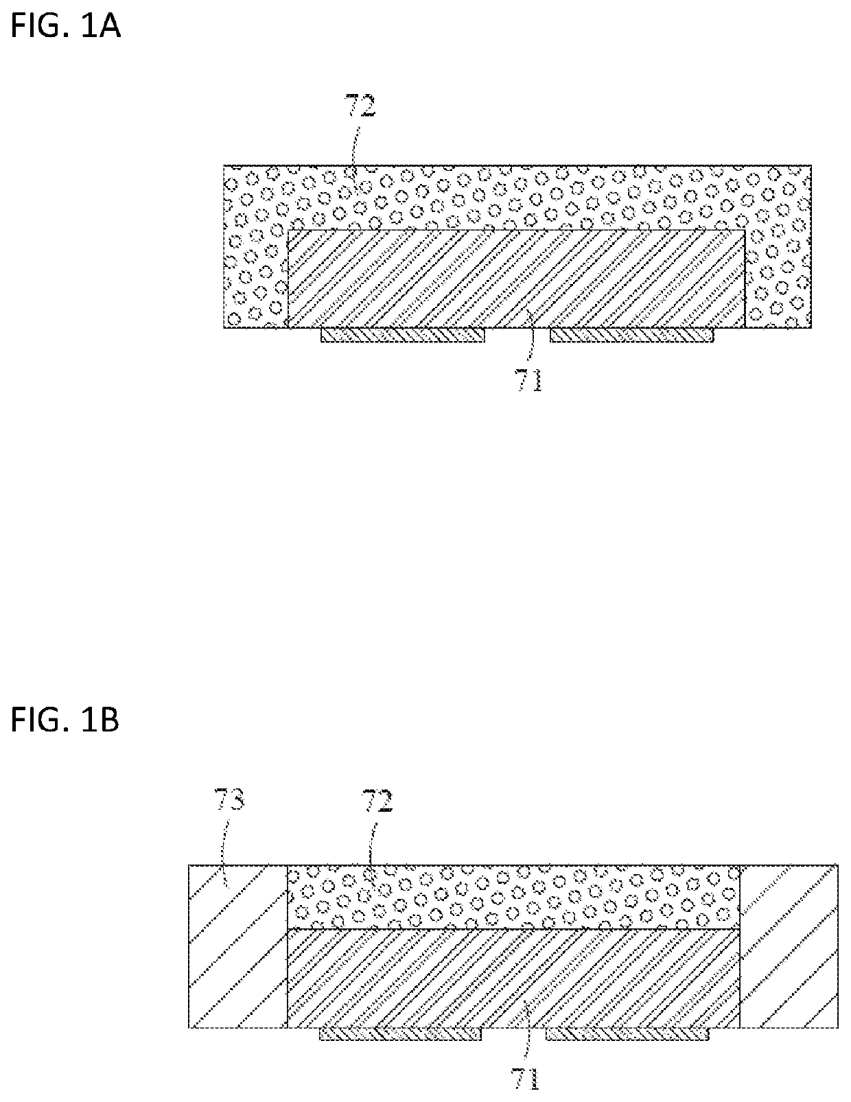
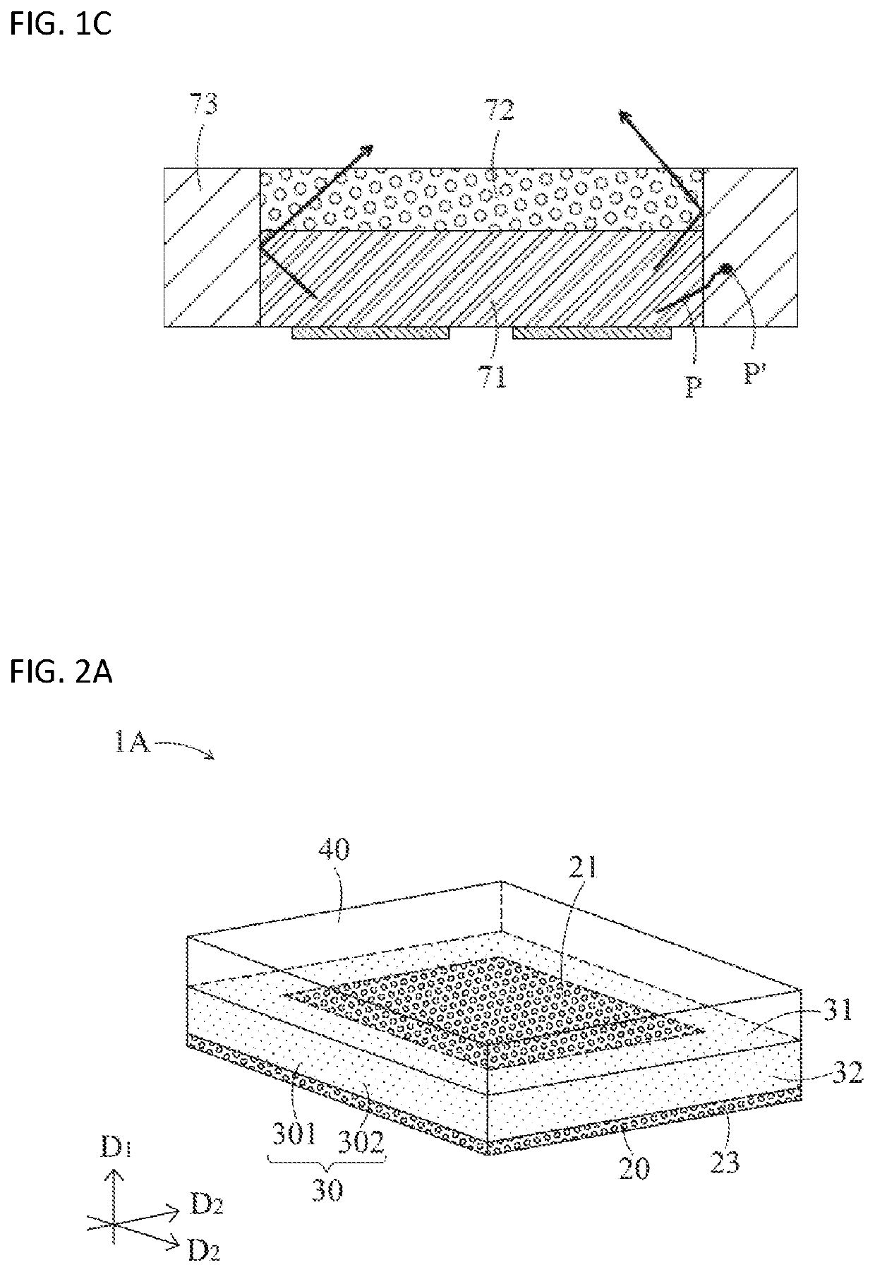
However, the reflective structure 73 made of this composition material is still not a very good reflector to rebound the light emitted from the LED semiconductor die 71 or the photoluminescent structure 72.
Photon dissipation inside the reflective structure 73 therefore degrades the optical efficacy of the CSP LED device.
The viewing angle or spatial radiation pattern can be adjusted to fit various applications without using an inefficient reflector, which will result in excessive optical energy dissipation because of the light trapped inside the CSP LED device structure.
As an example, when the BSS is strategically disposed surrounding the side edges of the CSP LED device, partial light originally travelling in the near horizontal direction of the LED semiconductor die is scattered to near vertical directions while passing through the BSS; however, the light originally travelling in near vertical direction will not experience the scattering effect of the BSS.

Method used


Image

  • Light emitting device with beam shaping structure and manufacturing method of the same
  • Light emitting device with beam shaping structure and manufacturing method of the same
  • Light emitting device with beam shaping structure and manufacturing method of the same

Examples


Embodiment Construction

Definitions

[0031]The following definitions apply to some of the technical aspects described with respect to some embodiments of the invention. These definitions may likewise be expanded upon herein.

[0032]As used herein, the singular terms “a,”“an,” and “the” include plural referents unless the context clearly dictates otherwise. Thus, for example, reference to a layer can include multiple layers unless the context clearly dictates otherwise.

[0033]As used herein, the term “set” refers to a collection of one or more components. Thus, for example, a set of layers can include a single layer or multiple layers. Components of a set also can be referred to as members of the set. Components of a set can be the same or different. In some instances, components of a set can share one or more common characteristics.

[0034]As used herein, the term “adjacent” refers to being near or adjoining. Adjacent components can be spaced apart from one another or can be in actual or direct contact with one a...


PUM

PropertyMeasurementUnit
viewing angleaaaaaaaaaa

Abstract

A chip scale packaging (CSP) light emitting diode (LED) device includes a flip-chip LED semiconductor die and a beam shaping structure (BSS) to form a monochromatic CSP LED device. A photoluminescent structure can be disposed on the LED semiconductor die to form a phosphor-converted white-light CSP LED device. The BSS is fabricated by dispersing light scattering particles with concentration equal to or less than 30% by weight into a polymer resin material, and is disposed adjacent to the edge portion of the photoluminescent structure or the LED semiconductor die; or disposed remotely above the photoluminescent structure or the LED semiconductor die. The BSS disposed at the edge portion of the device can reduce the edge-emitting light of the device; while the BSS disposed at the top portion of the device can reduce the top-emitting light of the device, therefore shaping the radiation pattern and the viewing angle of the device.

Description

CROSS-REFERENCES TO RELATED APPLICATIONS[0001]This application claims the benefit of and priority to Taiwan Patent Application No. 105104034 filed on Feb. 5, 2016 and Chinese Patent Application No. 201610082142.6 filed on Feb. 5, 2016, the disclosures of which are incorporated herein by reference in their entirety.BACKGROUND[0002]Technical Field[0003]The present disclosure relates to a light emitting device and the manufacturing method thereof, in particular to a chip-scale packaging light emitting device including a light emitting diode (LED) semiconductor die which generates electromagnetic radiation while it is in operation.[0004]Description of the Related Art[0005]Recent development of a chip-scale packaging (CSP) LED device has attracted more and more attention due to its promising advantages. As a typical example, a white-light CSP LED device as shown in FIG. 1A is generally composed of a flip-chip LED semiconductor die 71 and a photoluminescent structure 72 covering the LED s...

Claims


Application Information

Patent Timeline
Patent Type & Authority Patents(United States)
IPC IPC(8): H01L33/54H01L33/52H01L33/50H01L33/58H01L21/56
CPCH01L33/52H01L33/58H01L33/50H01L33/54H01L33/507H01L21/568H01L2933/0033H01L2933/0041H01L2933/005H01L2933/0058H01L2224/04105H01L2933/0091H01L2224/19H01L33/505H01L33/44H01L33/46
Inventor CHEN, CHIEHWANG, TSUNG-HSI
Owner MAVEN OPTRONICS CO LTD
Why Eureka
Eureka Blog
Learn More