Cutting sequence for net trimming a composite layup at an oblique angle

a composite material and oblique angle cutting technology, applied in the direction of metal working devices, etc., can solve the problems of dragging the composite material out of position, reducing the tendency of the cutting blade to bind the resin, and the cutting blade may adhere to the layup at an unacceptable rate,

Active Publication Date: 2008-04-10
THE BOEING CO
View PDF12 Cites 19 Cited by
  • Summary
  • Abstract
  • Description
  • Claims
  • Application Information

AI Technical Summary

Problems solved by technology

A disadvantage associated with conventional methods of cutting uncured composite layup is that a cutting blade may adhere to the layup and drag the composite material out of position.
The use of ultrasonic cutting blades reduces the tendency of the blade to bind the resin, however, for relatively thick layups or when cutting at an angle, conventional ultrasonic blades adhere to the layup at an unacceptable rate.

Method used


Image

  • Cutting sequence for net trimming a composite layup at an oblique angle
  • Cutting sequence for net trimming a composite layup at an oblique angle
  • Cutting sequence for net trimming a composite layup at an oblique angle

Examples


Embodiment Construction

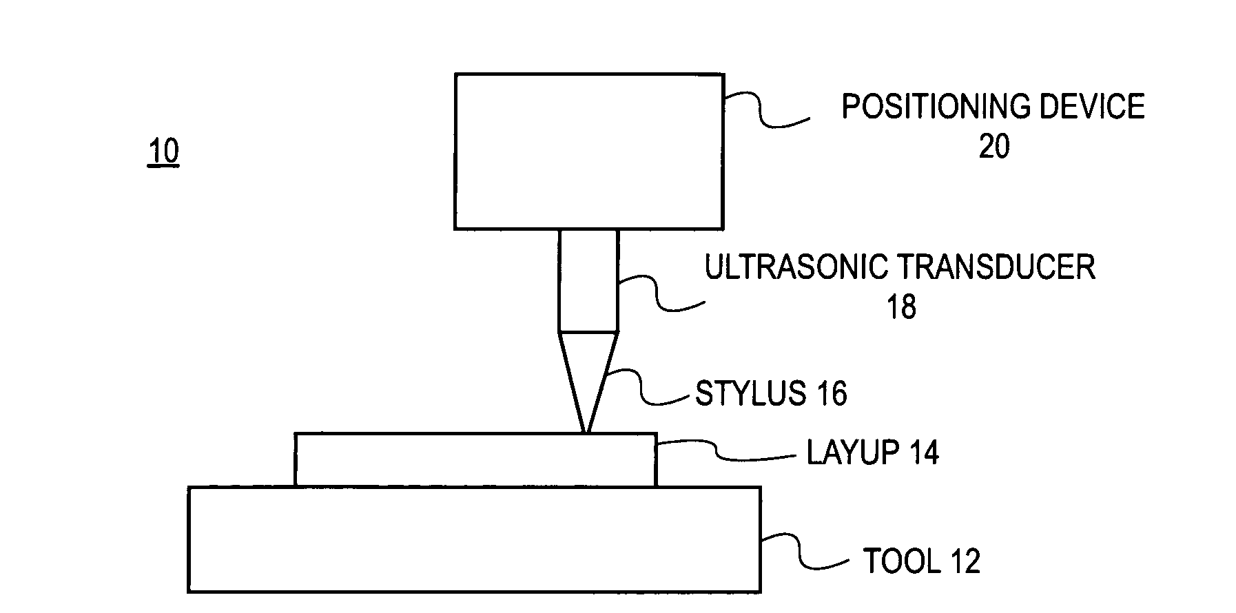
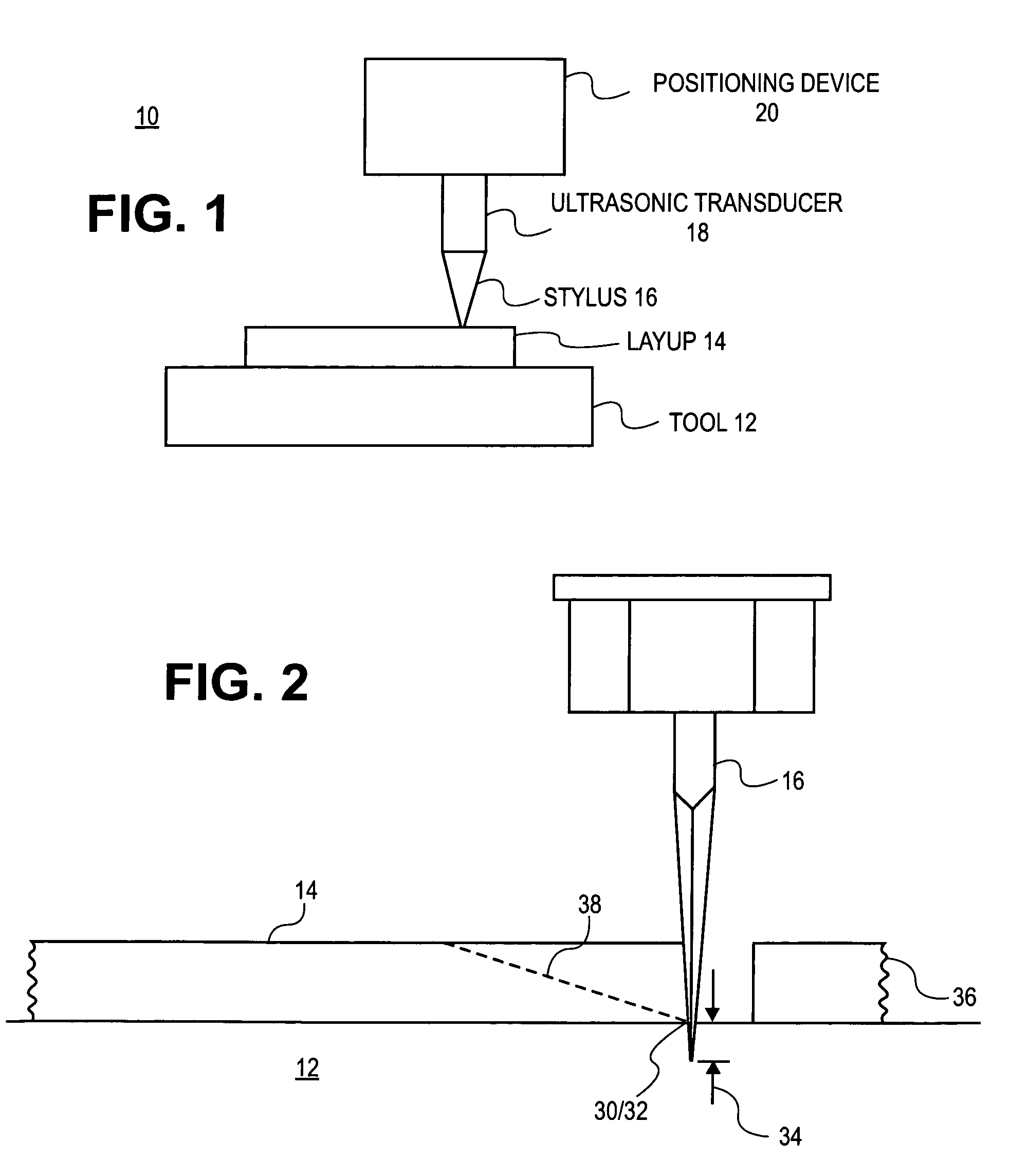
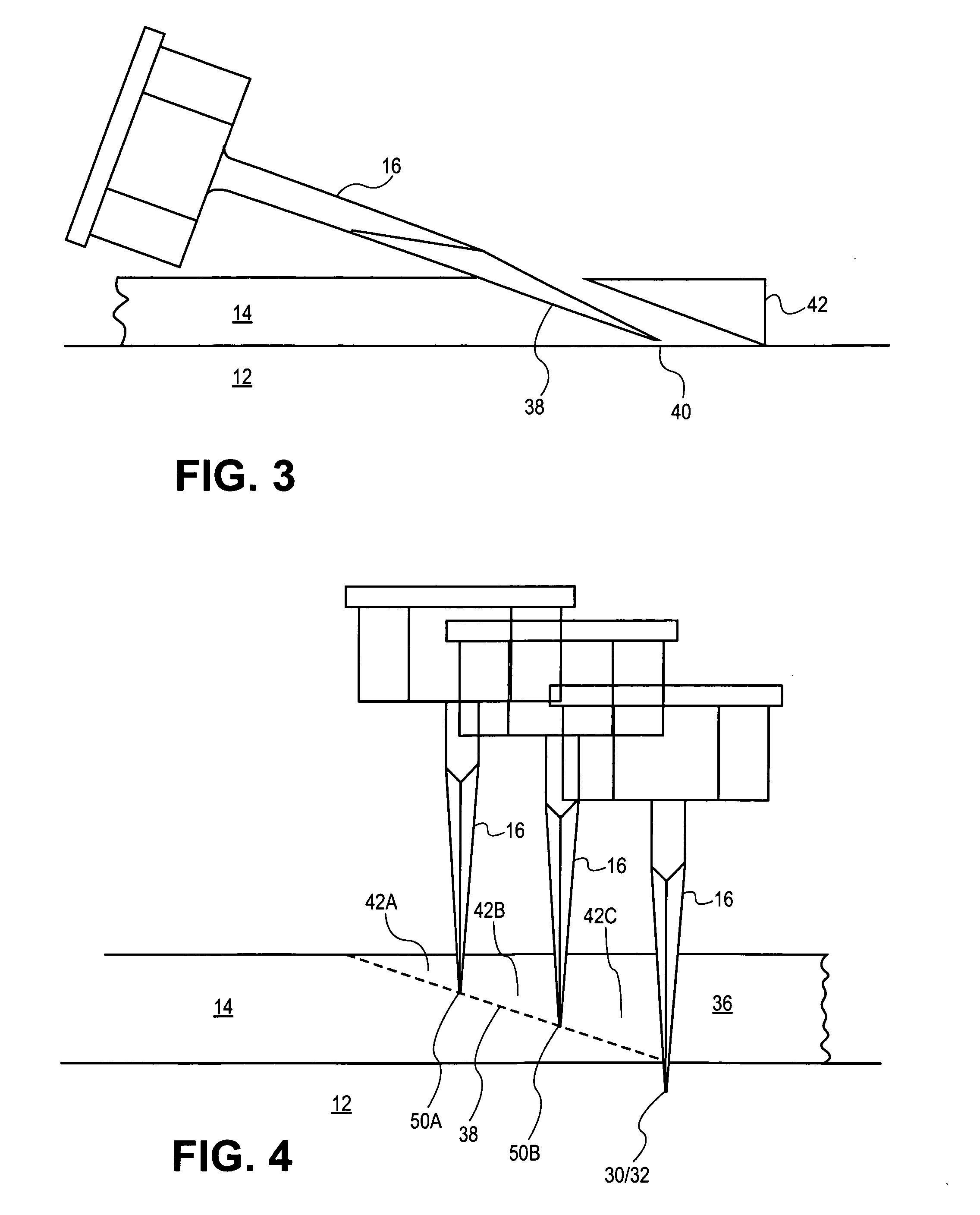
[0017]The present invention provides, in an embodiment, a method of net trimming or cutting a composite layup at an oblique angle. The composite layup or preform cut by this method include, at least, composite materials such as unidirectional tapes, fabrics, foils, and / or films that have been pre-impregnated with a resin “prepreg” and / or composite materials that have been otherwise bound or tacked together. In this embodiment, a sequence of cuts is performed that reduces drag upon a cutting blade. That is, resistance and adherence of the layup to the blade is reduced. By reducing drag, movement of the plies relative to other plies in the layup is reduced and bending force or deflection of the blade is reduced. In this manner, the sequence of cuts performed according to an embodiment of the invention increases accuracy of the final cut and minimizes disturbance of the layup, thereby, increasing production, reducing production cost, and decreasing waste associated with unacceptable mo...


PUM

PropertyMeasurementUnit
depthaaaaaaaaaa
incident angleaaaaaaaaaa
depthaaaaaaaaaa

Abstract

To generate a bevel in an uncured composite layup, an edge of part cut through the composite layup is performed at about 90° relative to the composite layup and a bevel cut is performed on the edge of part.

Description

FIELD OF THE INVENTION[0001]The present invention generally relates to a device and method of cutting composite material. More particularly, the present invention pertains to a method of net trimming a layup of composite ply material at an oblique angle and a device for doing so.BACKGROUND OF THE INVENTION[0002]Composite structures are typically constructed from multiple layers or plies. These plies may include a variety of materials such as carbon fiber, various other fibers, metal foils, and the like. In addition, the plies may be pre-impregnated with a resin and are often dispensed from a roll or spool. Typically, multiple plies are applied, one upon another, sometimes in multiple directions, to generate a “layup” of the composite item. This layup or “preform” is generally built up within a mold or over a form. Often, the plies are slightly oversized to ease the layup process. Depending upon the materials utilized and post-layup procedures that may be performed, any excess compos...

Claims


Application Information

Patent Timeline
Patent Type & Authority Applications(United States)
IPC IPC(8): B26D1/00B26D7/06
CPCB26D7/086B26D3/02Y10S83/956Y10T83/04Y10T83/0476Y10T83/0524Y10T83/8773
Inventor EVANS, RICHARD B.HEIGL, JOHN
Owner THE BOEING CO
Why Eureka
Try Eureka