Osteotomy plate, plate driver and method for their use

a technology of osteotomy and plate driver, applied in the field of osteotomy plate, can solve the problems of severe fracture and/or dislocation, development of problems, and often the subject of trauma to the midfoot, and achieve the effects of promoting bone insertion, good advantage of osteotomy, and reducing the width of the pla

Active Publication Date: 2011-01-13
ORTHOHELIX SURGICAL DESIGNS
View PDF22 Cites 77 Cited by
  • Summary
  • Abstract
  • Description
  • Claims
  • Application Information

AI Technical Summary

Benefits of technology

[0009]In accordance with the present invention an orthopedic plate (as well as a driver for the plate) is provided which can be used to good advantage in an osteotomy. In a first embodiment, the plate has a footprint that is a modified rectangle having a first end with rounded corners, and a longitudinally opposing end with a cutting edge that may include a taper or a crescent shape. Either two or three of the four sides of the plate, including both long sides and optionally the proximal end have a raised edge or rails which acts to stabilize the plate, and which is connected with a thinner flat web of material that includes one or more holes for screws or pins. At the cutting end, the rails may terminate in pointed insertion tips which are joined by the web that also includes a tapered cutting surface or the plate may simply include the tapered cutting edge. In a second embodiment, the plate has a simple bar-like footprint with a first end tab and a second end tab extending along the longitudinal axis of the plate and with narrowed waist sections between the tabs. At the...

Problems solved by technology

They are sophisticated, delicate and altogether elegant in function and design.
A structural flaw or malfunction in any one part can result in the development of problems, which are manifested in other areas of the body.
The mid-foot is often the subject of trauma, such as results...

Method used


Image

  • Osteotomy plate, plate driver and method for their use
  • Osteotomy plate, plate driver and method for their use
  • Osteotomy plate, plate driver and method for their use

Examples


first embodiment

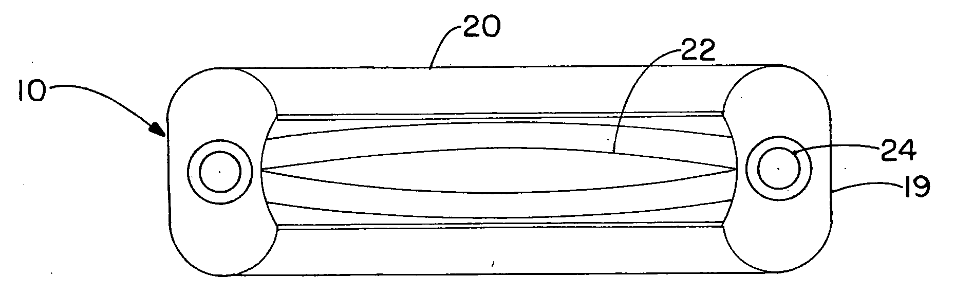
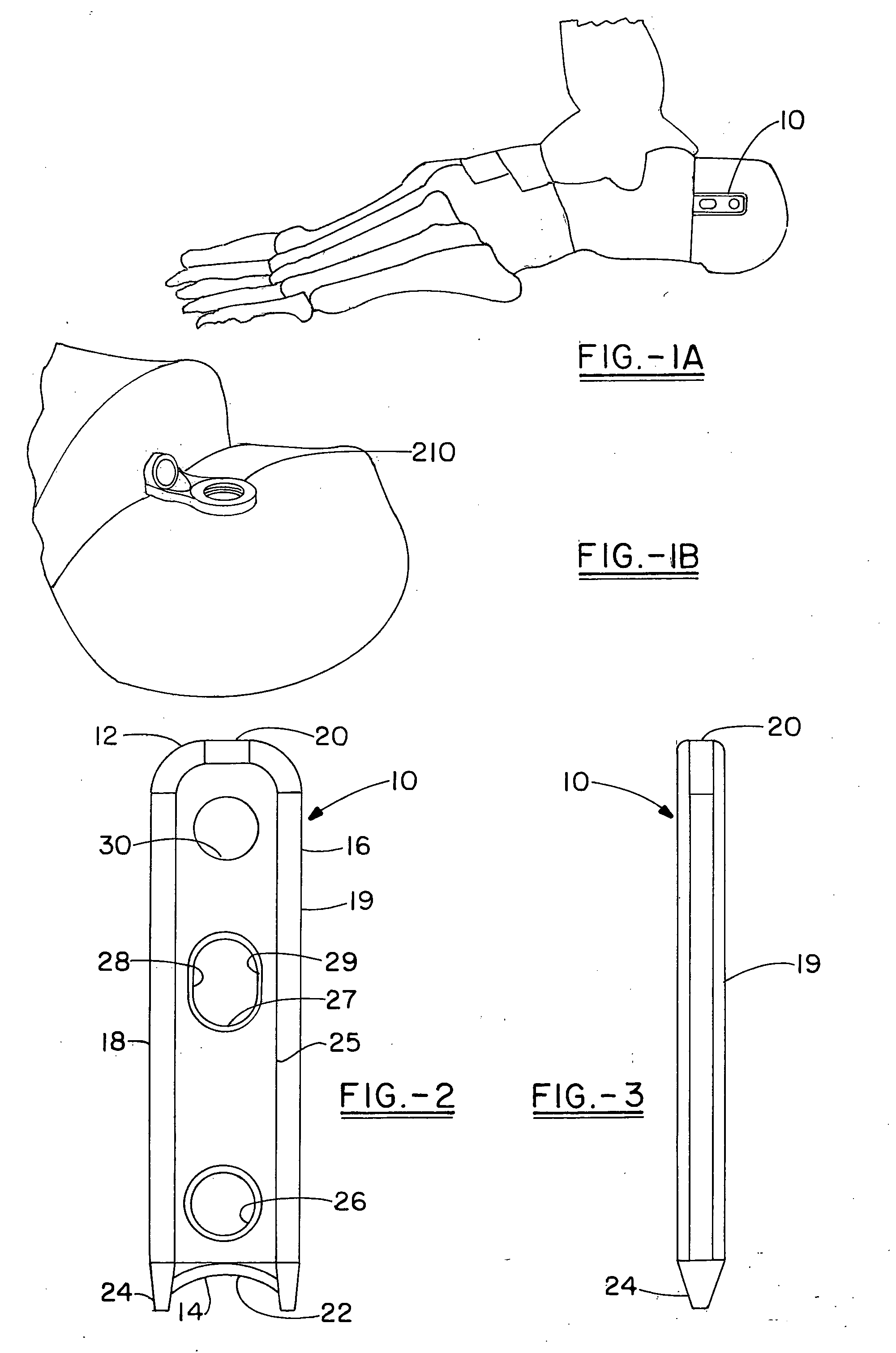
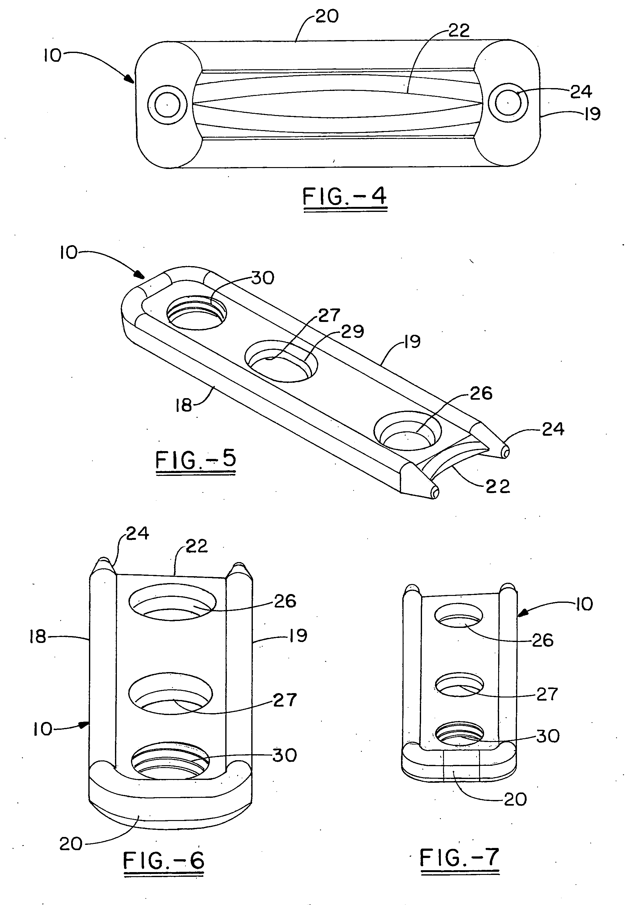
[0046]As viewed from the top in FIG. 2, it can be seen that the plate 10 has a rectangular shape with a first end 12 and an opposing cutting end 14 aligned along the longitudinal axis of the plate. The peripheral edges 16 of the plate are raised on three sides, including the two long sides 18, 19 and the squared short wall 20. These edges form rails that help to provide stability for the plate and in particular to inhibit torsion of the plate during insertion and during the recuperation period in which the injury fuses. The rails are rounded at the corners of the squared short wall 20. The opposing short wall includes a chamfered cutting surface 22, which is illustrated as a crescent shape between the two forward extending insertion tips 24 that are coextensive with the long wall edges. The body of the plate is formed by a thinner flat web 25 that extends between the raised edges and includes a number of openings. Preferably, the web 25 includes a first opening 26, or hole in the po...

second embodiment

[0047]In a second embodiment, the plate 110 has a simple bar-like profile that is comprised of a first end with a tab and a second end with a longer tab. The longer tab 112 has a rounded end at its proximal end that necks in slightly into the body of the first tab 112, and the rounded end includes a deep chamfer 115 which tapers from the lateral edge of the plate to an optional through hole 116 which can receive a screw or pin that helps to secure the plate in the cancellous portion of the bone against rotation or movement. The longer tab also includes an obround translation or compression slot 120 at the distal end of the first tab. The plate width Hairs slightly around the slot to preserve the metal which defines the slot (preferably to reinforce the slot to inhibit deformation of the slot during any option bending procedures, or even during insertion. Again the plate necks in slightly at the transition between the first tab and the second tab and the distal most 114 of the pair o...


PUM


Abstract

An orthopedic plate is specifically configured for use in osteotomies, in which part of the plate extends into a portion of a first bone segment and part is external to the cortical surface of an adjacent bone segment to fix the segments to allow them to fuse. The plate has a first end and a second end where the end which is inserted into the bone has a chamfer and a through hole having a hole axis optionally at an oblique angle to the longitudinal axis of the plate, and which can receive a screw, peg or pin. The second end of the plate includes a locking screw hole and optionally including a compression slot extending in a direction toward a screw hole in the opposing end. Optionally, the non-locking hole has a shroud that forms an arc or portion of a cylinder over the hole. A plate driver having a recess that holds the plate is used to insert the plate into the bone.

Description

CROSS REFERENCE[0001]This is a U.S. patent application of U.S. Provisional Application No. 61 / 270,486 filed on Jul. 9, 2009 for OSTEOTOMY PLATE AND METHOD FOR ITS USE which is hereby fully incorporated by reference.FIELD OF THE INVENTION[0002]The present invention relates to an orthopedic plate, which is configured for the fixation of a bone or bones of the foot, hand or wrist in particular following a procedure for fusion of adjacent segments or reconstruction such as various osteotomy procedures. The invention also relates to a surgical driver that is used to implant the osteotomy plate and to a method for the use of the orthopedic plate and associated driver in surgical reconstruction.BACKGROUND OF THE INVENTION[0003]The feet and the hands both include numerous bones and joints that cooperate together to define quintessential human movement. They are sophisticated, delicate and altogether elegant in function and design. Together the foot and ankle have over 25 bones and 33 joints...

Claims


Application Information

Patent Timeline
IPC IPC(8): A61B17/80
CPCA61B17/1728A61B17/8014A61B17/8052A61B17/8057A61B17/809A61B17/92A61B2017/1775A61B2017/1782A61B17/8061A61B17/1775A61B17/1782A61B17/8605A61B17/808
Inventor JOHNSON, JEFFREYKAY, DAVID B.HEAVENER, JACKSON R.
Owner ORTHOHELIX SURGICAL DESIGNS
Why Eureka
Try Eureka