
Vertically aligned liquid crystal display using polynorbornene based polymer film

Active Publication Date: 2005-09-01
LG CHEM LTD
View PDF7 Cites 72 Cited by
  • Summary
  • Abstract
  • Description
  • Claims
  • Application Information

AI Technical Summary

Benefits of technology

[0004] In view of these problems, the present invention provides a vertically aligned liquid crystal display (VA-LCD) including liquid crystals with negative dielectric anisotropy (Δε<0) and a polarization plate for viewing angle compensation that can enhance viewing angle characteristics. The polarization plate can perform optical compensation for wide viewing angles using a polynorbornene based polymer film with negative birefringence in its thickness direction even without a film stretching process. Therefore, high contrast characteristics for front view and oblique angle view are realized and color change for oblique angle view is minimized.
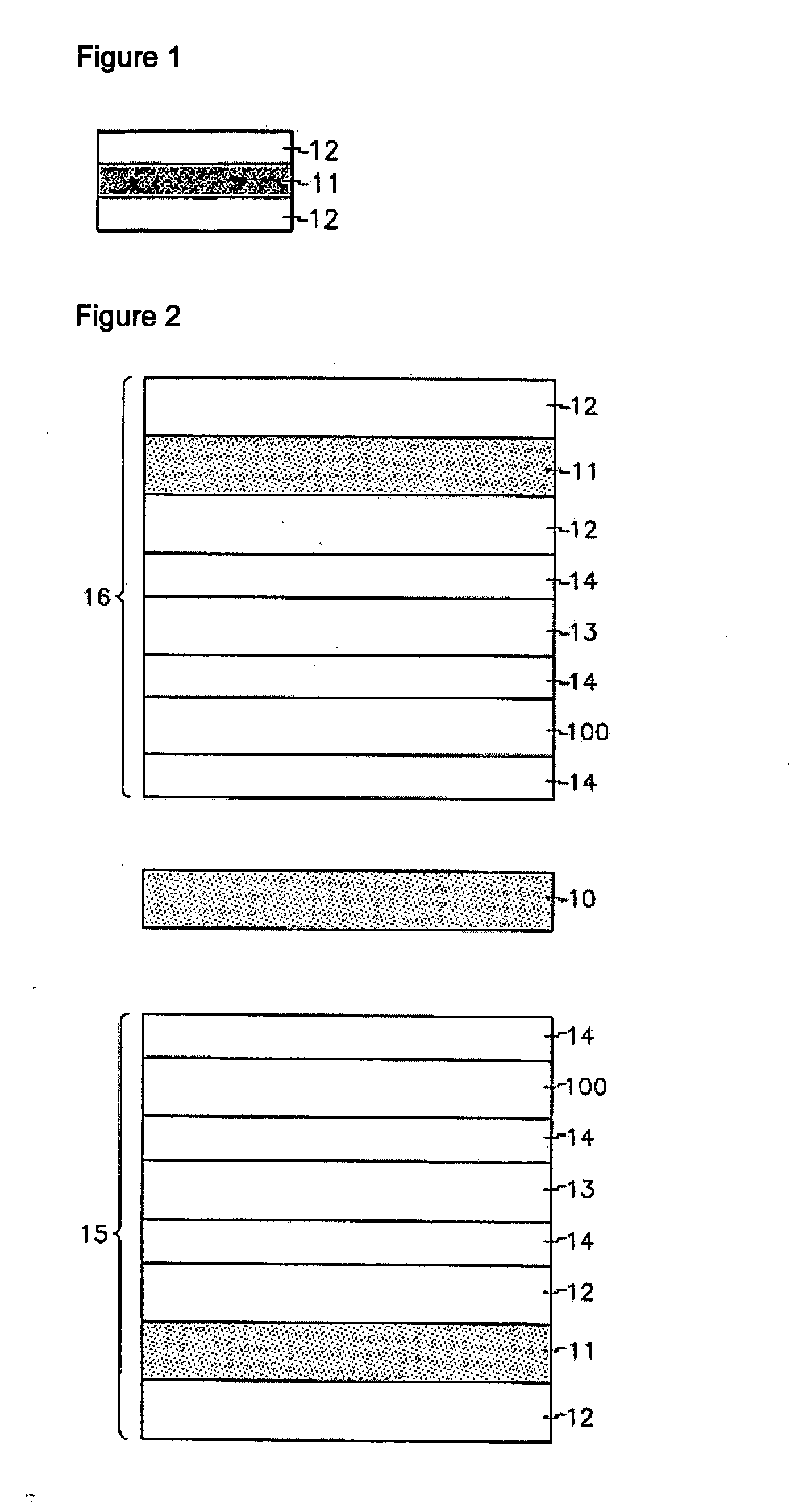
[0016] In detail, a VA-LCD of the present invention includes a vertically aligned panel (VA panel) and polarization plates disposed on both sides of the VA panel. In particular, a polarization plate disposed on a side of the VA panel has a fundamental structure of protection film 12 / polarization film 11 / protection film 12, like a common polarization plate as shown in FIG. 1. An outer protection film must be made of a transparent material with 90% or more of visible light transmittance and have good moisture resistance and bond strength. An inner protection film must be made of a transparent material with 90% or more of visible light transmittance and have good heat resistance, small elastic modulus, small film deformation, and good bond strength.
[0020] Furthermore, the polynorbornene based polymer film has low moisture absorptivity and good bond strength with a polyvinylalcohol (PVA) polarization film, thereby ensuring good durability. Therefore, the polynorbornene based polymer film can also be used as a protection film for a polarization film.
[0130] Therefore, a VA-LCD of the present invention can provide high contrast characteristics for a front view and an oblique angle view and minimize color change for an oblique angle view.

Problems solved by technology

However, VA-LCDs including only a negative C-plate compensation film have a disadvantage of light leakage at an oblique angle due to imperfect viewing angle compensation.

Method used


Image

  • Vertically aligned liquid crystal display using polynorbornene based polymer film
  • Vertically aligned liquid crystal display using polynorbornene based polymer film
  • Vertically aligned liquid crystal display using polynorbornene based polymer film

Examples


example 1

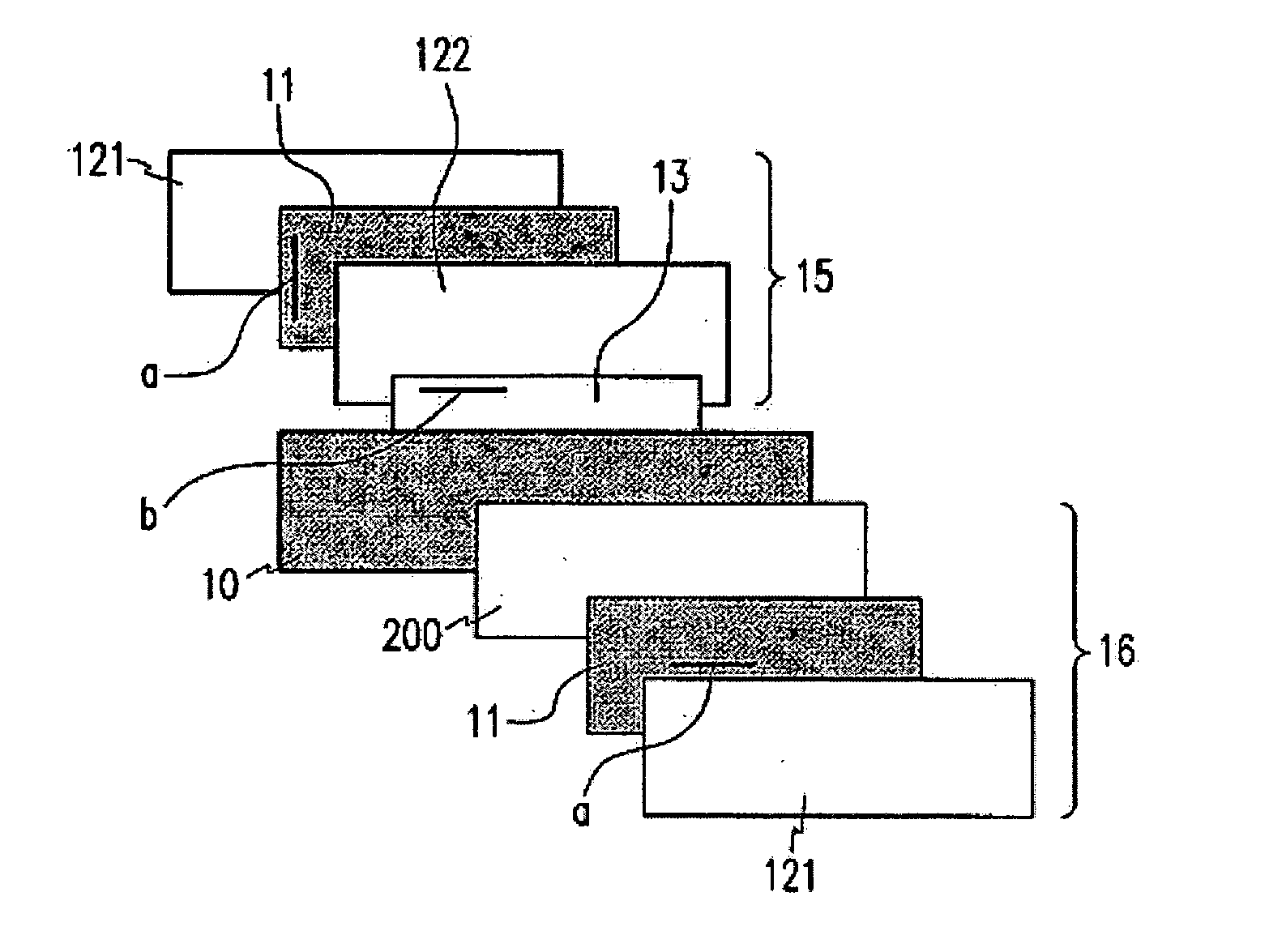
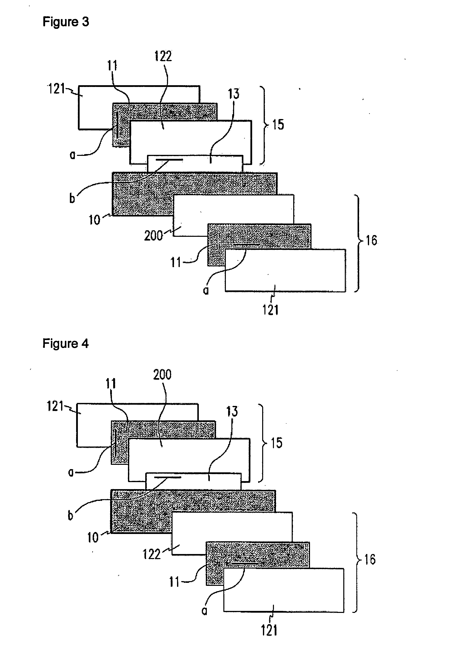
[0156] Like the structure of FIG. 3, there was manufactured a vertically aligned liquid crystal display (VA-LCD) including a polynorbornene based polymer film serving both as a protection film and as a negative C-plate for an upper polarization plate. In FIG. 3, a reference symbol a is the absorption axis of a polarization plate and a reference symbol b is the slow axis of an A-plate.

[0157] A VA panel contained VA cells having a cell gap of 3 μm and a pre-tilt angle of 89 degrees and being filled with liquid crystals with negative dielectric anisotropy ofΔε=−4.9 and birefringence of Δn=0.099. The thickness retardation value (RVA(550 nm)) of the VA panel was 297 nm.

[0158] A lower polarization plate included, from bottom to top, an outer protection film made of a TAC polymer, a polarization film formed by dying a polyvinylalcohol (PVA) film with iodine followed by stretching, an inner protection film made of a TAC polymer, and an A-plate film made of polycarbonate. At this time, the...

example 2

[0161] Like the structure of FIG. 4, there was manufactured a VA-LCD including a polynorbornene based polymer film serving both as a protection film and as a negative C-plate for a lower polarization plate. In FIG. 4, a reference symbol a is the absorption axis of a polarization plate and a reference symbol b is the slow axis of an A-plate.

[0162] A VA panel contained VA cells having a cell gap of 3 μm and a pre-tilt angle of 89 degrees and being filled with liquid crystals with negative dielectric anisotropy of Δε=−4.9 and birefringence of Δn=0.099. The thickness retardation value (RVA(550 nm)) of the VA panel was 297 nm.

[0163] The lower polarization plate included, from bottom to top, an outer protection film made of a TAC polymer, a polarization film formed by dying a PVA film with iodine followed by stretching, a polynorbornene based polymer film serving both as an inner protection film and as a negative C-plate film, and an A-plate film made of polycarbonate. At this time, the...

example 3

[0166] Like the structure of FIG. 5, there was manufactured a VA-LCD including a polynorbornene-based polymer film serving both as an inner protection film and as a negative C-plate for an upper polarization plate and a lower polarization plate. In FIG. 5, a reference symbol a is the absorption axis of a polarization plate and a reference symbol b is the slow axis of an A-plate.

[0167] A VA panel contained VA cells having a cell gap of 3 μm and a pre-tilt angle of 89 degrees and being filled with liquid crystals with negative dielectric anisotropy of Δε=−4.9 and birefringence of Δn=0.099. The thickness retardation value (RVA(550 nm)) of the VA panel was 297 nm.

[0168] The lower polarization plate included, from bottom to top, an outer protection film made of a TAC polymer, a polarization film formed by dying a PVA film with iodine followed by stretching, a polynorbornene based polymer film serving both as an inner protection film and as a negative C-plate film, and an A-plate film m...


PUM


Abstract

Provided are a vertically aligned liquid crystal display (VA-LCD) with good viewing angle characteristics, which has liquid crystals with negative dielectric anisotropy (Δε<0). In the VA-LCD, a polynorbornene based polymer film is used as a protection film and / or as a negative C-plate retardation film for an upper polarization plate and / or a lower polarization plate. Therefore, high contrast characteristics for a front view and an oblique angle view are realized and color change for an oblique angle view can be minimized.

Description

TECHNICAL FIELD [0001] The present invention relates to a liquid crystal display (LCD) with excellent viewing angle characteristics. More particularly, the present invention relates to a vertically aligned LCD (VA-LCD) including liquid crystals with negative dielectric anisotropy (Δε<0). BACKGROUND ART [0002] A negative C-plate compensation film used in common liquid crystal displays (LCDs) is disclosed in U.S. Pat. No. 4,889,412. A main function of the negative C-plate compensation film is to compensate for the black state of vertically aligned LCDs (VA-LCDs) under no voltage application. However, VA-LCDs including only a negative C-plate compensation film have a disadvantage of light leakage at an oblique angle due to imperfect viewing angle compensation. [0003] Combination of a negative C-plate compensation film and an A-plate compensation film is disclosed in U.S. Pat. No. 6,141,075. According to the technology disclosed in this patent, good viewing angle compensation of the ...

Claims


Application Information

Patent Timeline
IPC IPC(8): G02F1/1335G02F1/13363G02F1/1337G02F1/137G02F1/139
CPCG02F1/133634G02F2001/13712G02F1/1393G02F1/13712G02F1/1335
Inventor JEON, BYOUNG-KUNYU, JEONG-SUBELYAEV, SERGEYKIM, WON-KOOKCHUN, SUNG-HOYOON, SUNG-CHEOLLIM, TAE-SUNKIM, HEONLEE, JUNG-MIN
Owner LG CHEM LTD
Learn More