Angular velocity detection apparatus

Inactive Publication Date: 2008-04-10
RICOH IMAGING COMPANY
View PDF15 Cites 10 Cited by
  • Summary
  • Abstract
  • Description
  • Claims
  • Application Information

AI Technical Summary

Benefits of technology

[0007]Therefore, an object of the present invention is to provide an angular velocity detection apparatus that corrects the output error caused by the undesired angle of inclination of the angular velocity sensor.

Problems solved by technology

However, the output error caused by the undesired angle of the inclination resulting from the imperfect alignment, during installation, of the angular velocity sensor for the anti-shake operation is not considered.

Method used


Image

  • Angular velocity detection apparatus
  • Angular velocity detection apparatus
  • Angular velocity detection apparatus

Examples


Embodiment Construction

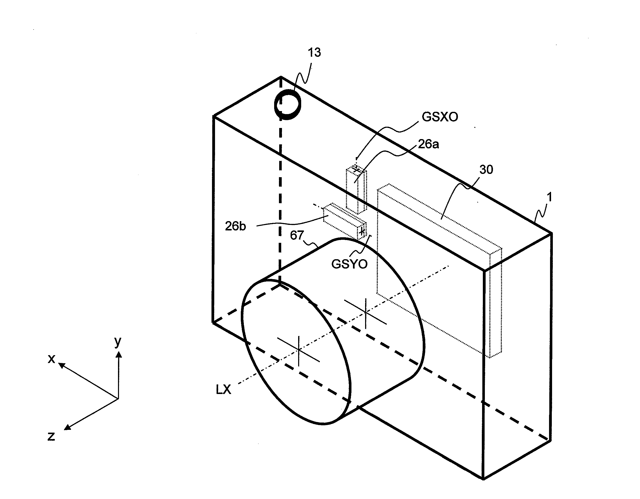
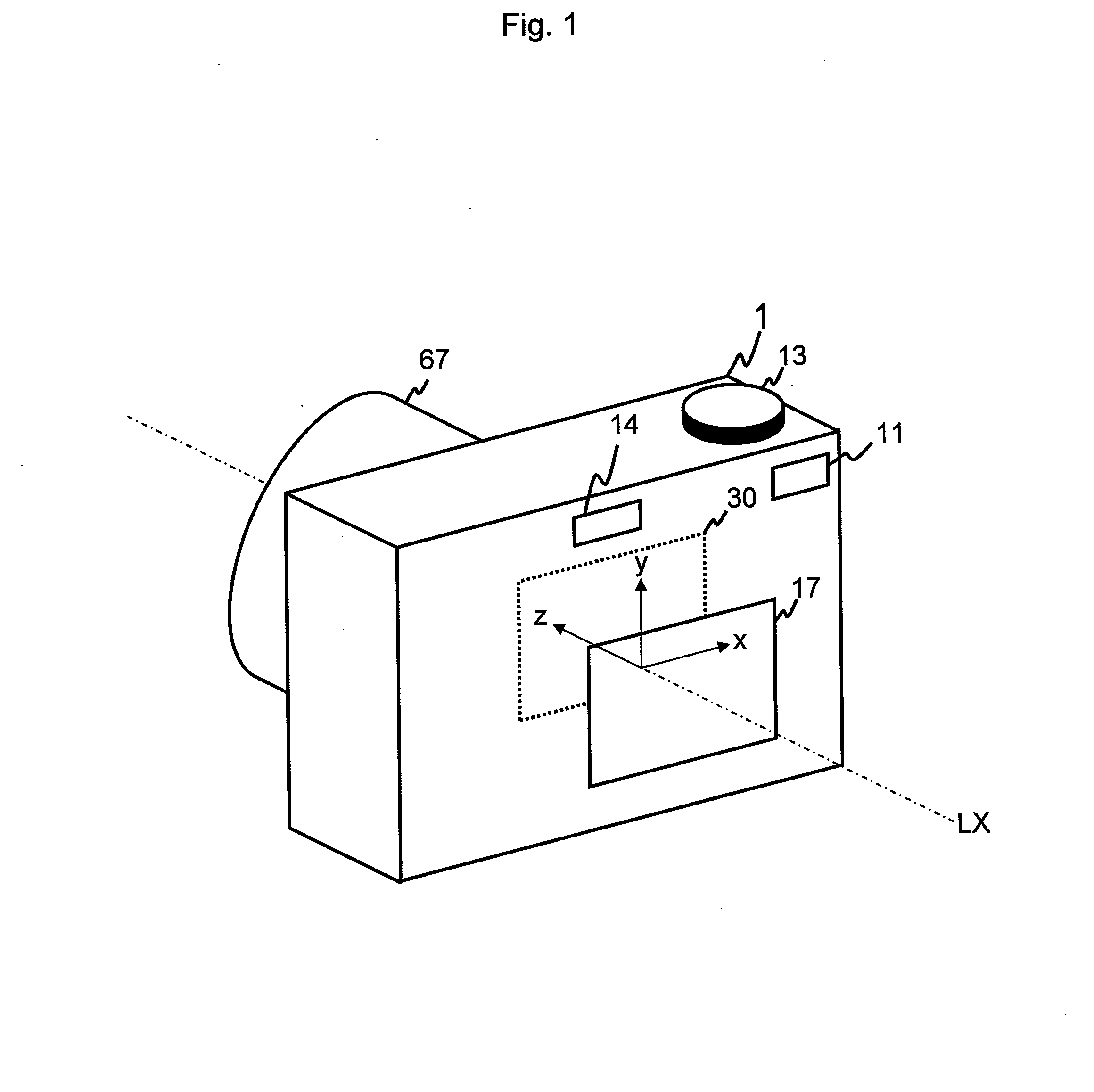
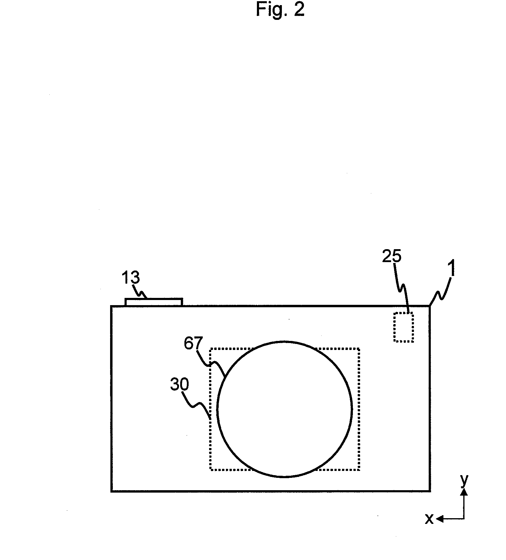
[0018]The present invention is described below with reference to the embodiment shown in the drawings. In the embodiment, the photographing apparatus 1 is a digital camera. A photographing optical system, such as a camera lens 67 etc. that captures (images) an optical image on a photographing surface of the imaging device of the photographing apparatus 1, has an optical axis LX.

[0019]In order to explain the direction in the embodiment, a first direction x, a second direction y, and a third direction z are defined (see FIG. 1). The first direction x is perpendicular to the optical axis LX. The second direction y is perpendicular to the optical axis LX and the first direction x. The third direction z is parallel to the optical axis LX and perpendicular to both the first direction x and the second direction y.

[0020]The imaging part of the photographing apparatus 1 comprises a PON button 11, a PON switch 11a, a photometric switch 12a, a release button 13, a release switch 13a, an anti-s...


PUM


Abstract

An angular-velocity detector comprises a first sensor, a second sensor, and a controller. The first sensor is used for detecting motion around an axis of a second direction perpendicular to a first direction. The second sensor is used for detecting motion around an axis of the first direction. The controller performs an operation that corrects an output error caused by an angle of inclination of the second sensor by using a first correction coefficient that is a ratio of a second amplitude to a first amplitude. The first amplitude is amplitude of output value from the first sensor when the angular-velocity detector is in first motion around an axis of the second direction without second motion around an axis of the first direction. The second amplitude is amplitude of output value from the second sensor when the angular-velocity detector is in the first motion without the second motion.

Description

BACKGROUND OF THE INVENTION[0001]1. Field of the Invention[0002]The present invention relates to an angular velocity detection apparatus, and in particular to the modification of an output error caused by an undesired angle of inclination resulting from the imperfect alignment, during installation, of the angular velocity sensor for the anti-shake operation etc.[0003]2. Description of the Related Art[0004]An anti-shake apparatus for a photographing apparatus is proposed. The anti-shake apparatus corrects for hand-shake effects by moving either a hand-shake correcting lens that is a part of the photographing optical system, or an imaging device, on a plane that is perpendicular to the optical axis of the photographing optical system, in a manner corresponding to the amount of hand-shake that occurs during the imaging process.[0005]Japanese unexamined patent publication (KOKAI) No. H09-80552 discloses an anti-shake apparatus that reduces noise and improves the precision of the hand-sh...

Claims


Application Information

Patent Timeline
Patent Type & Authority Applications(United States)
IPC IPC(8): H04N5/228
CPCG03B5/00G03B2205/0007H04N23/687
Inventor UENAKA, YUKIO
Owner RICOH IMAGING COMPANY
Why Eureka
Try Eureka