Operation guarantee system

a technology of operation guarantee and guarantee circuit, which is applied in the direction of information storage, static storage, digital storage, etc., can solve the problems of time major errors may occur, and the lag between data and clock signals can be a major cause of errors, so as to prevent the occurrence of output errors in the signal processing circuit and ensure the operation of the electronic apparatus

Inactive Publication Date: 2010-07-22
PANASONIC CORP
View PDF10 Cites 6 Cited by
  • Summary
  • Abstract
  • Description
  • Claims
  • Application Information

AI Technical Summary

Benefits of technology

[0037]According to the present invention, the occurrence of the output error in the signal processing circuit can be prevented by operating the first storage circuit based on the value of the first operating condition stored in the second storage circuit even though the value of the second operating condition varies in the range within the first threshold value. Accordingly, the first threshold value is set to the appropriate value to determine the value of the first operating condition with which the appropriate operation margins of the first storage circuit and the signal processing circuit can be obtained. As a result, the operations of the first storage circuit and the signal processing circuit can be appropriately guaranteed.
[0038]In addition, when the operation guarantee system is applied to the system board, the value of the first operating condition appropriate for the system board can be recognized based on the value of the first operating condition stored in the second storage circuit. This allows the system board to be appropriately selected according to the use environment and so on of the electronic apparatus in which the system board is to be used, so that the operation of the electronic apparatus can be appropriately guaranteed.

Problems solved by technology

While the data and the clock signal are transmitted through conductor patterns within the system board, a time lag may occur between the data and the clock signal due to various causes.
In the foregoing memory that processes a large number of signals at high speed, such a time lag between the data and the clock signal may be a major cause of error occurrences.

Method used


Image

  • Operation guarantee system
  • Operation guarantee system
  • Operation guarantee system

Examples


Embodiment Construction

[0059]Description will be made of an operation guarantee system according to embodiments of the present invention by referring to the drawings. Note that a television receiver including the operation guarantee system will be described in the following paragraphs.

(1) Configuration of Television Receiver

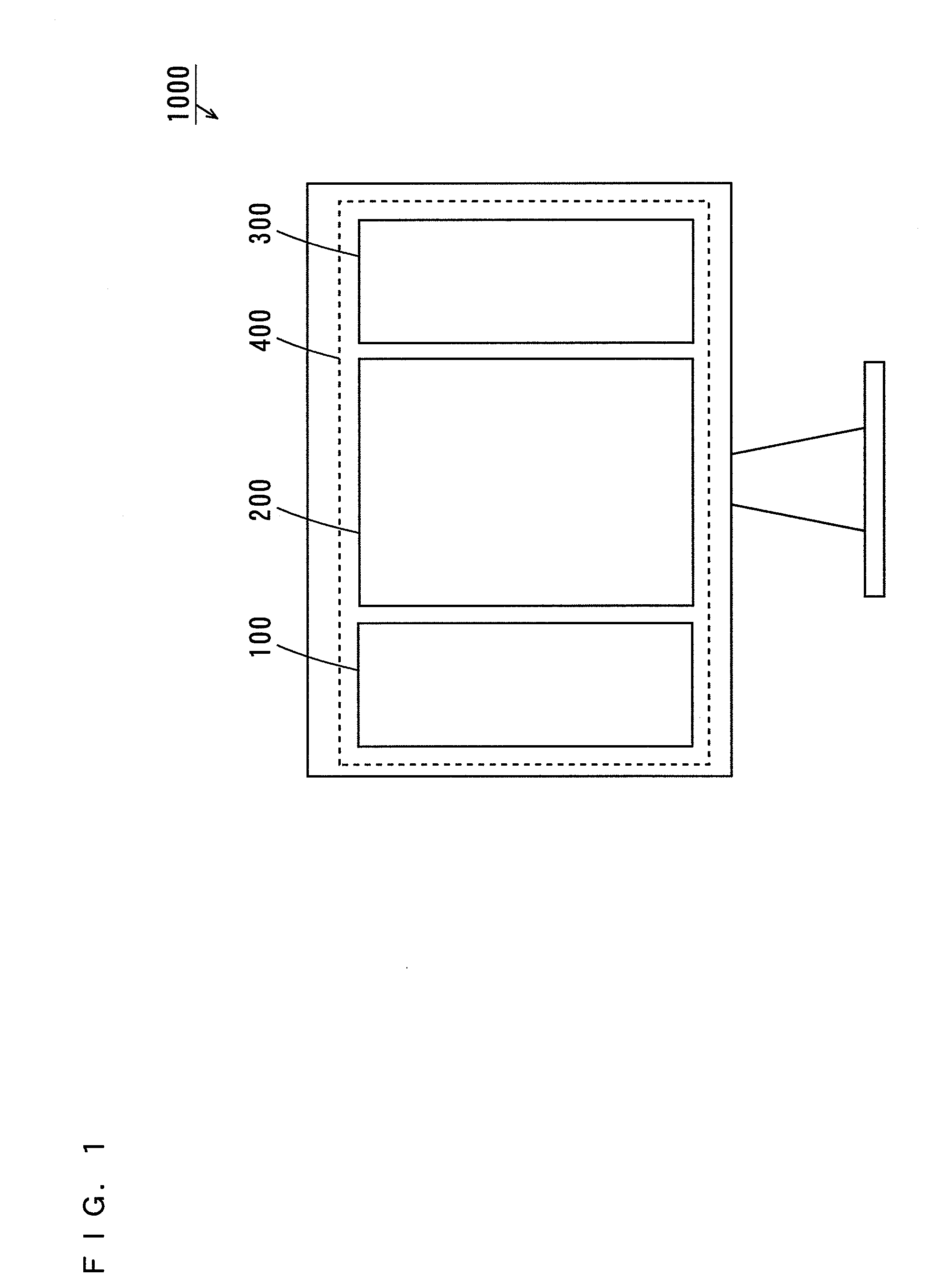
[0060]FIG. 1 is a schematic rear view showing a television receiver including an operation guarantee system according to an embodiment of the present invention.

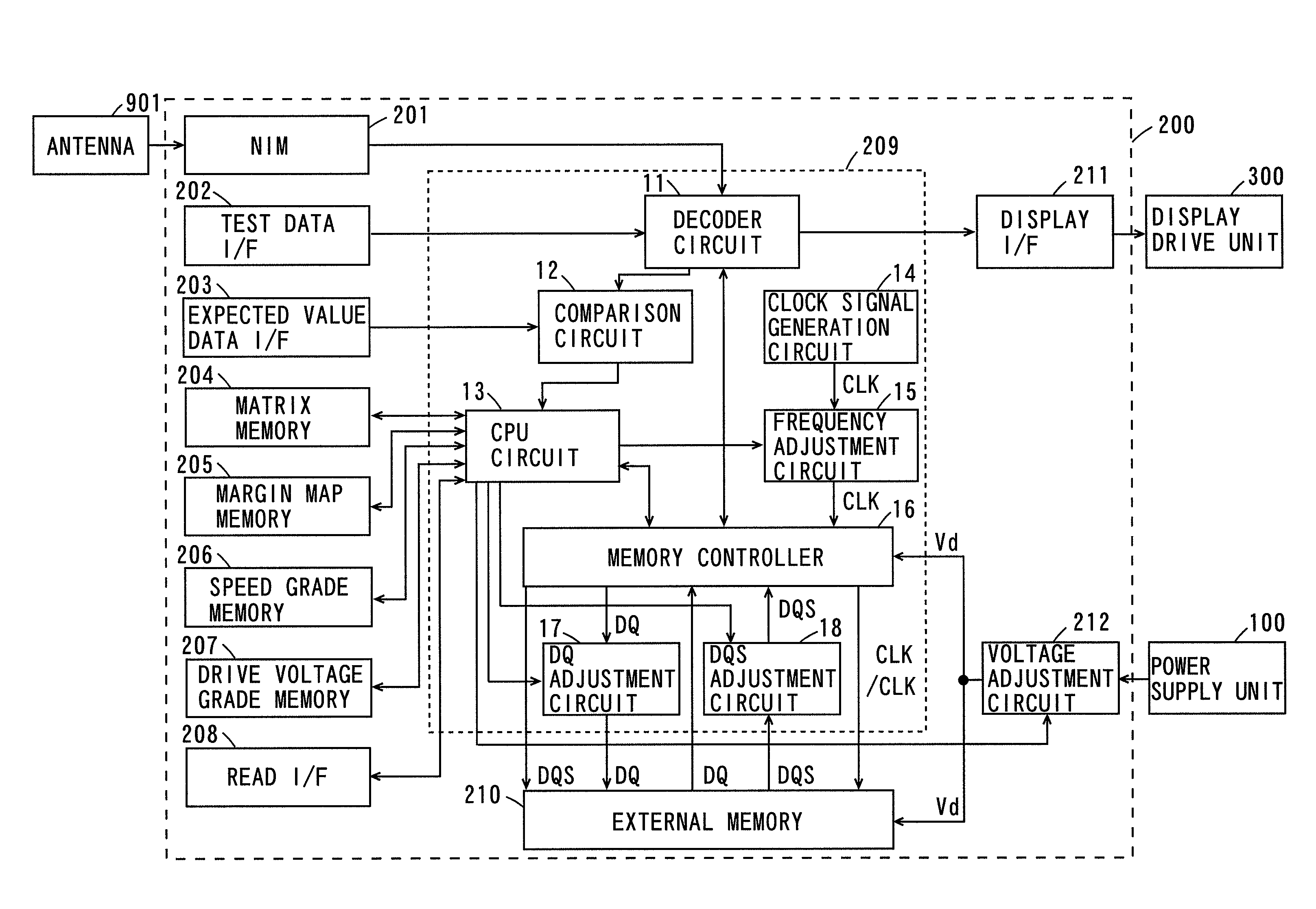
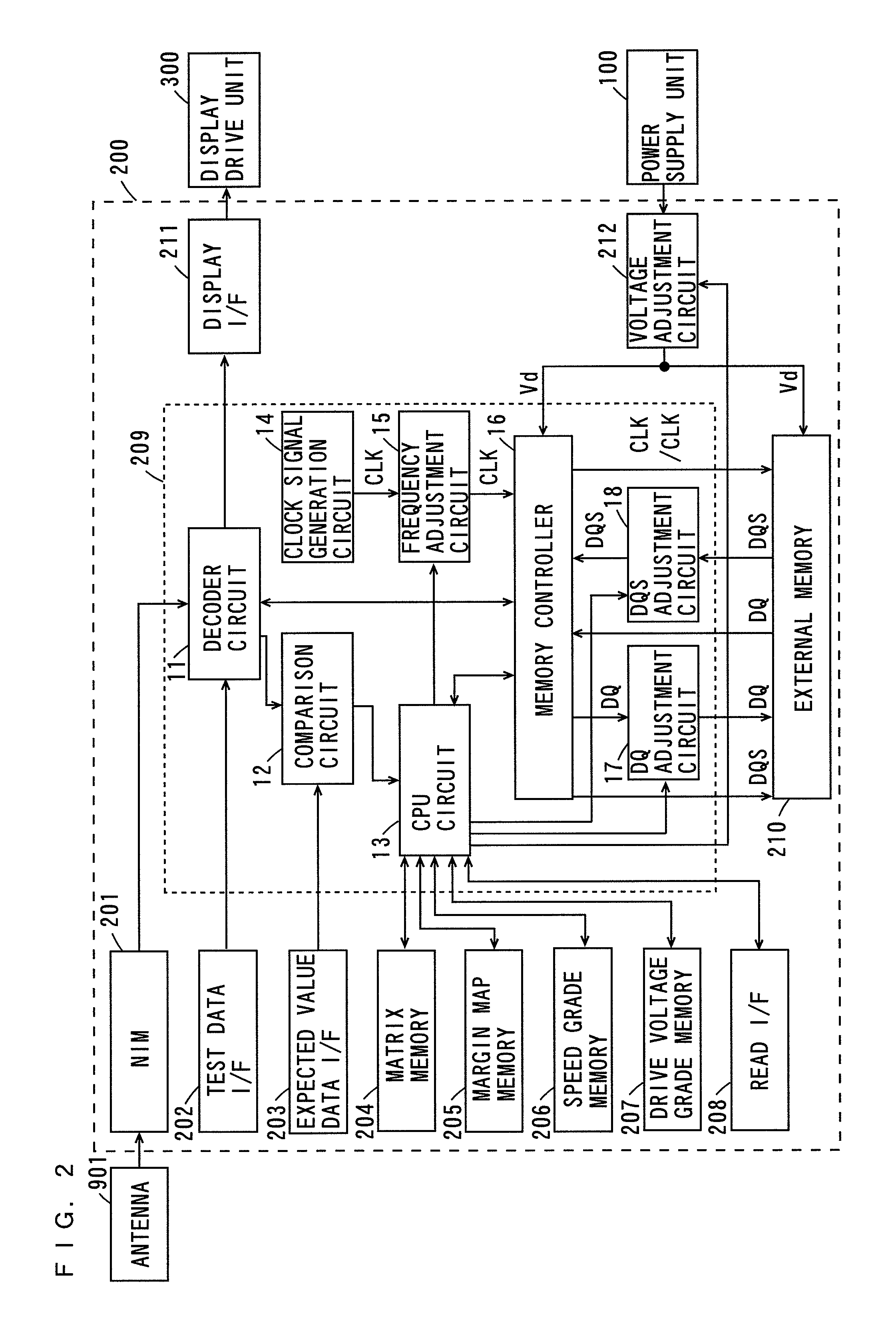
[0061]As shown in FIG. 1, a power supply unit 100, a system board 200 and a display drive unit 300 are provided on a rear side of the television receiver 1000. A display 400 such as a plasma display panel (PDP), a liquid crystal display (LCD) or a cathode ray tube (CRT) is provided on a front side of the television receiver 1000. In addition, a sound output device (not shown) such as a speaker is provided on the front side of the television receiver 1000.

[0062]The power supply unit 100 is connected to a commercial power supply t...


PUM


Abstract

An operation guarantee system includes a decoder circuit, a comparison circuit, a CPU circuit, a frequency adjustment circuit and a DQ adjustment circuit. The comparison circuit compares a test data signal input from the decoder circuit with an expected value data signal input from the exterior, and detects the presence or absence of an output error in the decoder circuit. The CPU circuit controls the frequency adjustment circuit and the DQ adjustment circuit to vary a frequency of a clock signal input to an external memory and a delay amount of the data signal. In addition, the CPU circuit acquires a result of detection of the comparison circuit under various conditions. Then, the CPU circuit determines an appropriate frequency of the clock signal input to the external memory based on a relationship between the various conditions and the presence or absence of the output error.

Description

TECHNICAL FIELD[0001]The present invention relates to an operation guarantee system that guarantees an operation of a system board and or the like.BACKGROUND ART[0002]In multifunctional and high-performance electronic apparatuses, a large number of digital signals need to be processed at high speed, and therefore highly integrated system LSIs (Large Scale Integrated Circuits) are mounted. In recent years, there have been developed various memories such as a DDR-SDRAM (Double Data Rate Synchronous Dynamic Random Access Memory) with high processing speed that are applicable to such highly integrated system LSIs.[0003]In the electronic apparatuses or the like, the system LSI and the memory are electrically connected to each other on a common board. Hereinafter, the board on which the system LSI and the memory are mounted is referred to as a system board.[0004]Writing data from the system LSI in the memory and reading data from the memory to the system LSI are executed in synchronizatio...

Claims


Application Information

Patent Timeline
Patent Type & Authority Applications(United States)
IPC IPC(8): G11C7/00
CPCG11C7/1051G11C7/1066G11C7/1072G11C7/222G11C29/022G11C29/023G11C29/028G11C2207/2254
Inventor TAKATORI, MASAHIRO
Owner PANASONIC CORP
Why Eureka
Try Eureka