Router plane

a router and router technology, applied in the direction of large fixed members, dovetail work, manual wood tools, etc., can solve the problems of difficult to accurately and repeatably adjust the depth of cut and the position of the blade, and the alternative of lateral positioning of the blade or cutter is also limited, so as to facilitate precise blade positioning and adjustment, quick and easy blade removal or reorientation, and reduce backlash

Active Publication Date: 2008-04-10
LEE VALLEY TOOLS
View PDF40 Cites 2 Cited by
  • Summary
  • Abstract
  • Description
  • Claims
  • Application Information

AI Technical Summary

Benefits of technology

[0006]The router plane of this invention preferably utilizes a generally square cross-section blade shaft or shank that is mountable in either of two alternative locations in the body and in multiple rotational positions in the outboard or bullnose location. The blade shaft is secured to the body with an appropriately shaped collar that accommodates the multiple rotational positions and can be rotated relative to the body to permit the shaft to be secured in either of the two alternative positions. The spring-loaded blade-clamping collar holds the blade in position when the collar is loosened and provides tactile feedback for controlled blade depth adjustment. The collar can also be made to fully release by pressing the collar-tightening thumb screw forward after rotating it to loosen it for quick and easy blade removal or reorientation. The blade can be positioned in front of the post (inboard of the plane body) for general work, behind the post (outboard of the body) for bullnose applications or laterally (left or right) for work on hinge gains.
[0007]The collar is located on a body post that has a projecting rim. This rim and the pin structure associated with the collar together limit upward travel of the collar so that the collar cannot be removed without removing the body post from the body. The blade is secured to the body with the collar utilizing a locking knob having a shaft threaded into the collar and to which a spring loaded, telescoping locking pin is attached in such a manner that the locking collar will be held snugly in position even when the locking knob is not fully tightened. This reduces backlash during blade adjustment, facilitating precise blade positioning and adjustment. Protrusions located on the inside surface of the collar contact the blade shaft in a manner that insures that the blade accurately aligns itself with one of two V-grooves in the body post rather than by reference to the collar itself.

Problems solved by technology

Notwithstanding such improvements, the depth of cut and position of blades have often been difficult to adjust accurately and repeatably in prior router planes.
Alternatives for lateral positioning of the blade or cutter have also been limited.

Method used


Image

  • Router plane
  • Router plane
  • Router plane

Examples


Embodiment Construction

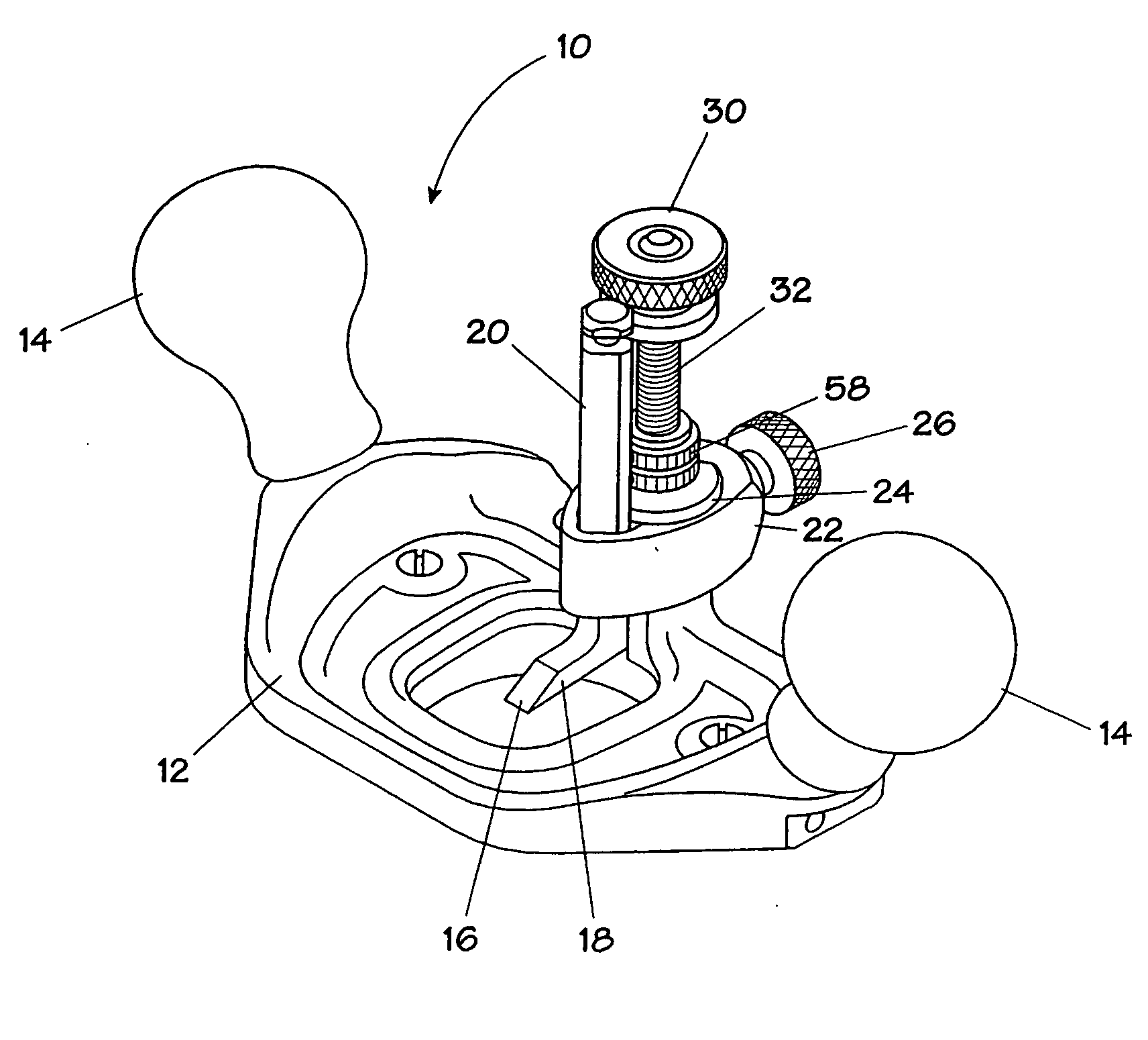
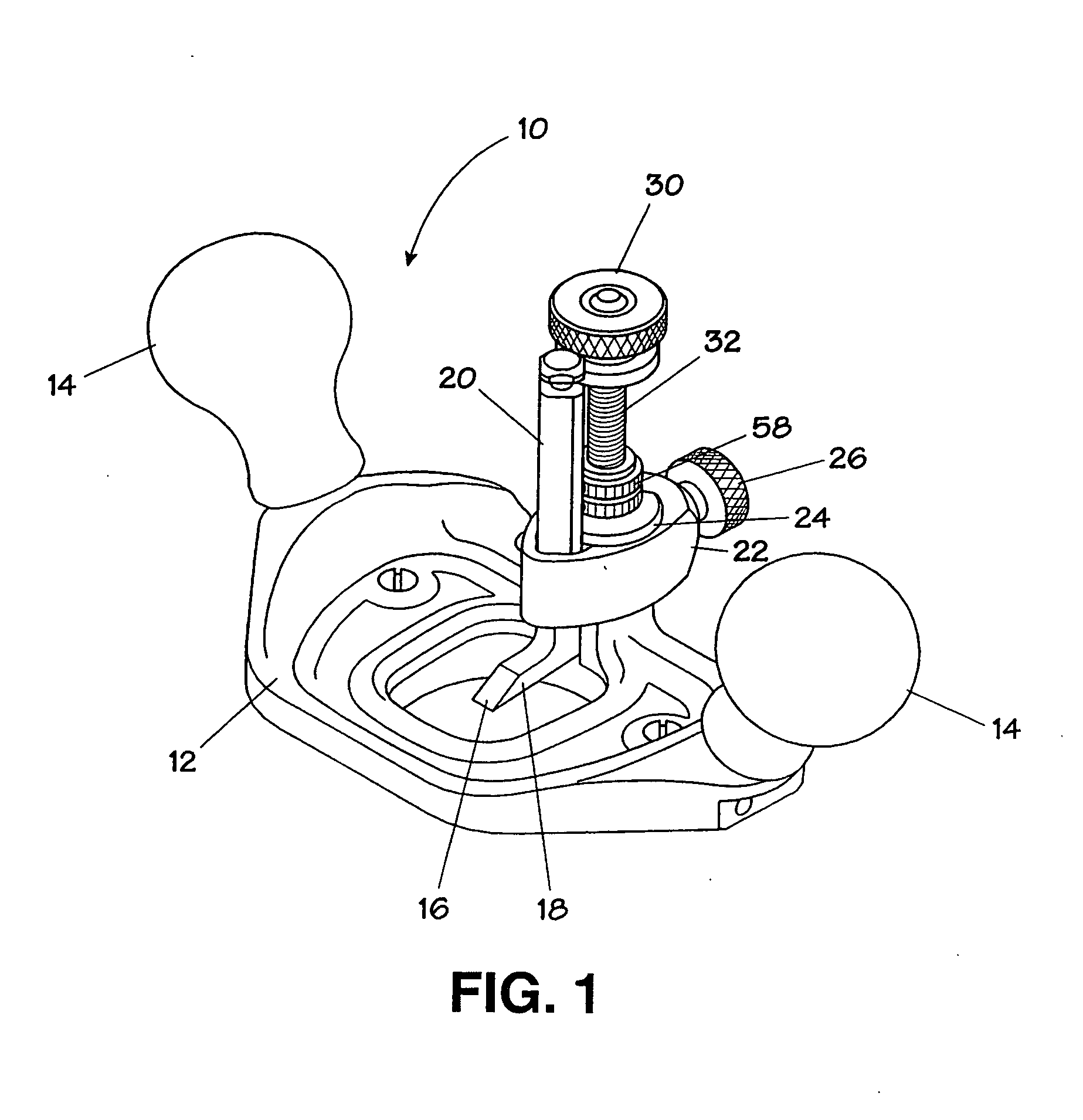
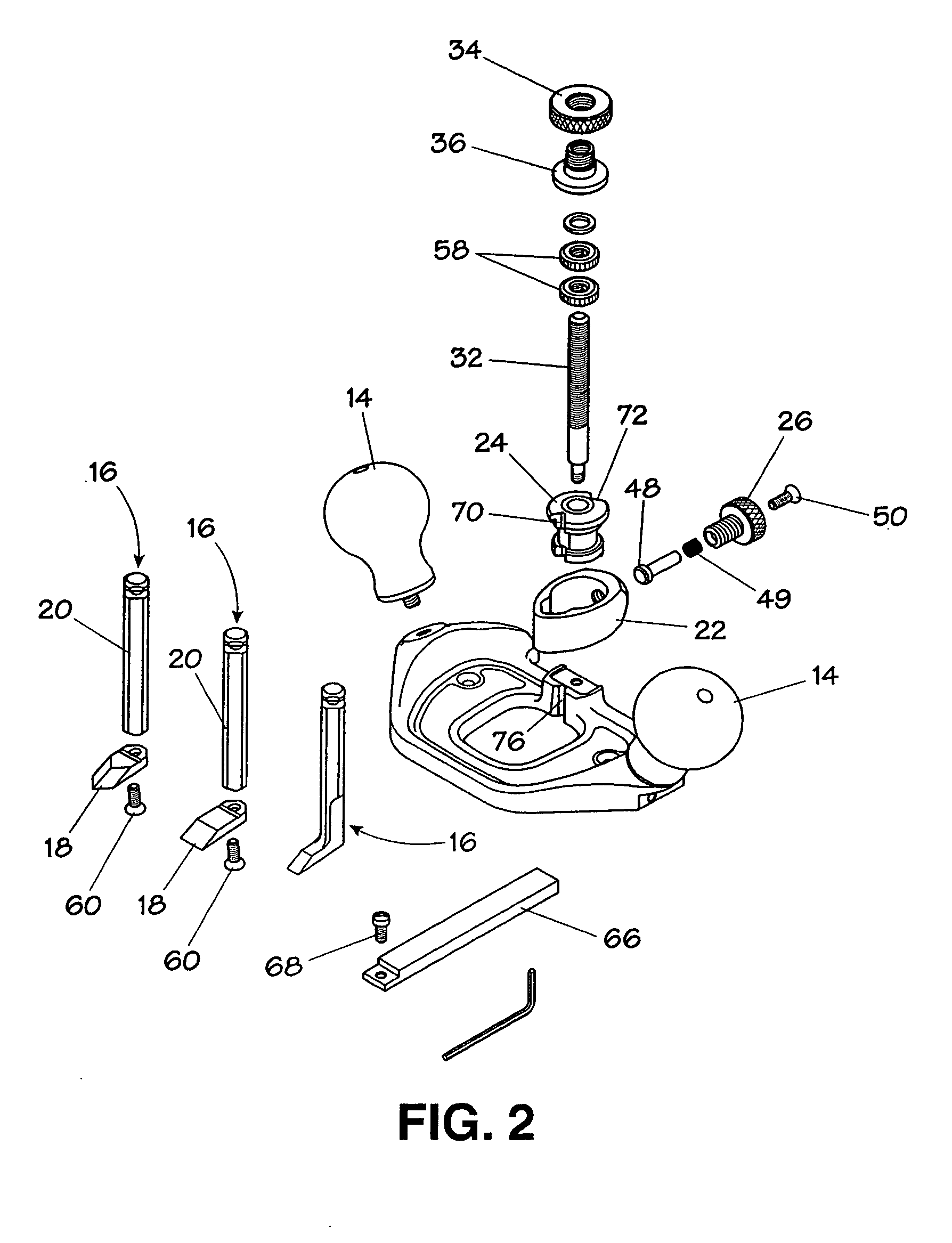
[0016]In the figures, a router plane 10 exemplary of this invention has a plane body 12 manipulated with knobs 14 to cause a blade 16 to engage a work piece (not shown) as desired. Blade 16 has a foot 18 attached to a shank or shaft 20. Shaft 20 is secured to plane body 12 with a collar 22 that encircles the shaft 20 and clamps it against a body post 24 by rotating a thumb screw 26. The projection of blade 16 beyond the sole 28 of body 12 can be adjusted in small increments by rotating blade adjustment knob or thumb nut assembly 30 which is threaded onto a threaded adjustment post 32.

[0017]Blade adjustment assembly 30 may be fabricated in one piece or it may be, as illustrated in FIG. 2, two pieces: a knurled knob 34 (which can be brass) and an internally threaded disk 36 (that can be steel) that has a washer-shaped flange 38 that engages a neck 40 near the top of shaft 20 to drive shaft 20, 20′, or 20″ up or down by rotating knurled knob 34.

[0018]As can be appreciated by reference ...


PUM

PropertyMeasurementUnit
angleaaaaaaaaaa
frictionaaaaaaaaaa
depth of cutaaaaaaaaaa

Abstract

A router plane having a collar maintained in snug engagement with a blade shank during blade height adjustment to facilitate accurate adjustment with a threaded adjustment nut that travels on an adjustment post. The collar is retained on a post secured to the router plane body so that the collar can rotate between blade in-board and blade out-board positions without removal from the post.

Description

FIELD OF THE INVENTION[0001]This invention relates to manual or hand router planes.BACKGROUND OF THE INVENTION[0002]Router planes or routers are fitted with a relatively narrow cutter and are generally used to form or refine a recess in a work piece. Typically a body having a sole for contact with a work piece is held and manipulated by two handles or knobs attached to the body, and a cutter having a cutting arris on a foot projecting from a the cutter shank is secured to the body to project below the sole.[0003]The blade or cutter in router planes has usually been a sharpened foot projecting at approximately a right angle from a shank or shaft that is secured in the plane body in a position orthogonal to the router sole. Such a blade is usually secured to an upstanding post portion of the plane body also orthogonal to the router sole, typically with a collar that encircles the blade shaft or shank and upstanding post, and a thumbscrew threaded into the collar bears against the post...

Claims


Application Information

Patent Timeline
Patent Type & Authority Applications(United States)
IPC IPC(8): B23P15/28
CPCY10T407/22B27G17/02
Inventor SAUNDERS, TERRY R.SMITH, EWAN
Owner LEE VALLEY TOOLS
Why Eureka
Try Eureka