Taylor series-based transmission line equalization scheme

Active Publication Date: 2008-04-10
ANALOG DEVICES INC
View PDF1 Cites 0 Cited by
  • Summary
  • Abstract
  • Description
  • Claims
  • Application Information

AI Technical Summary

Benefits of technology

[0009]The kl terms in this H−1(f) expression serve as weighting factors which vary with the length of the conductor. Using the Taylor series expansion as the basis for the equalization, along with the use of weighting factors that adjust the equalization for varying li

Problems solved by technology

Generally, equalization schemes have been implemented digitally; the absolute accuracy of the equalization schemes provided by

Method used


Image

  • Taylor series-based transmission line equalization scheme
  • Taylor series-based transmission line equalization scheme
  • Taylor series-based transmission line equalization scheme

Examples


Embodiment Construction

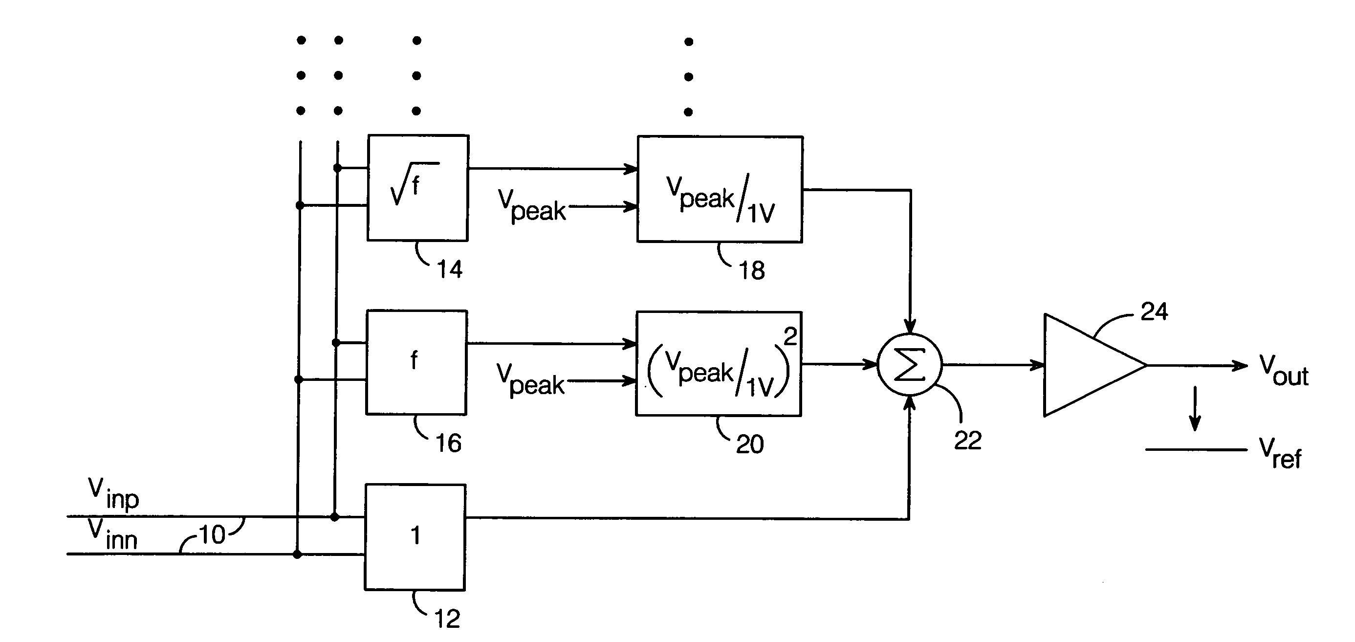
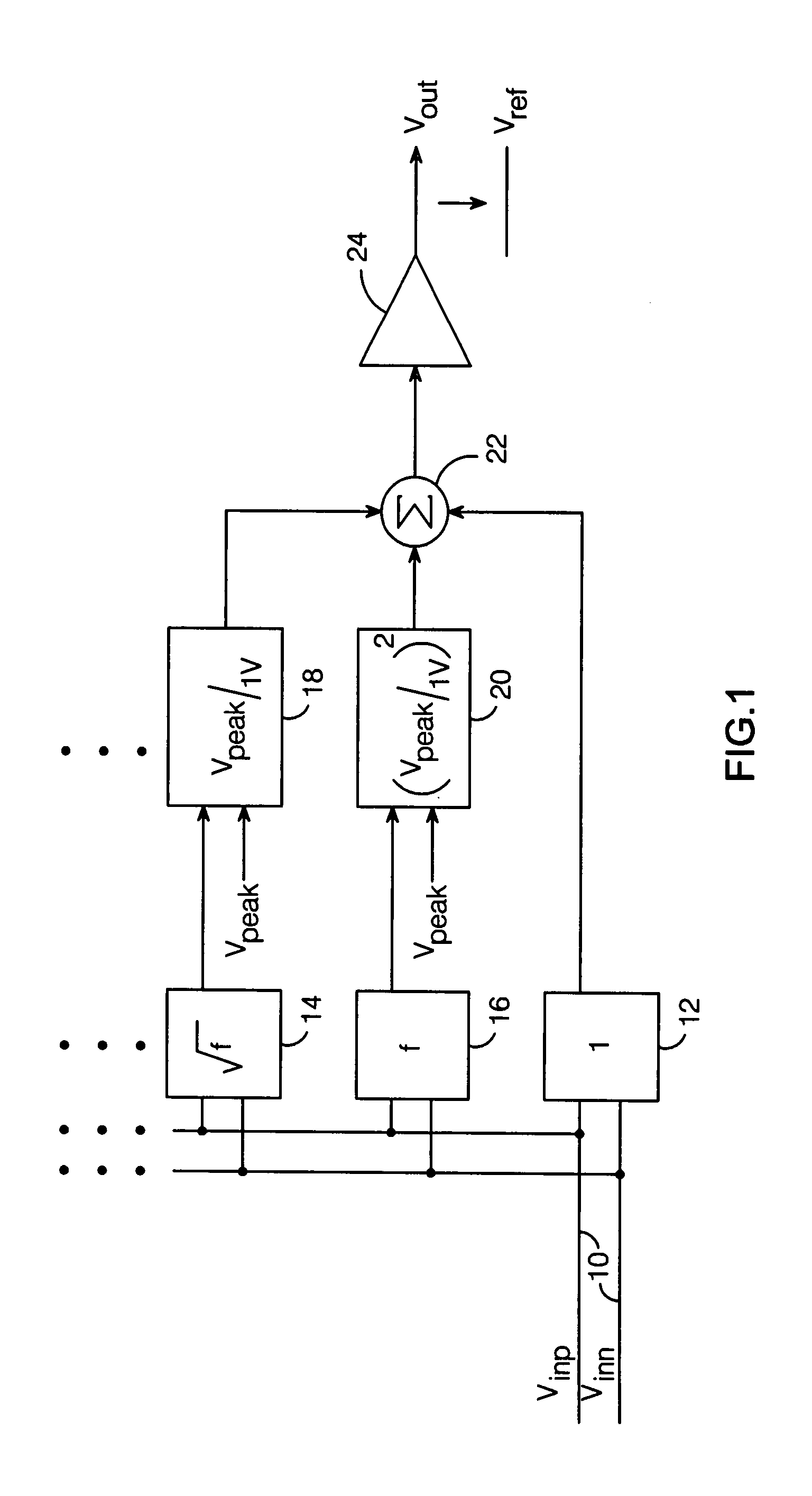
[0020]It is known from transmission line theory that the impedance of a good conductor increases by the square root of frequency due to the skin effect. The equation describing the frequency response of a good conductor is given by:

H(f)=e−kl(1+j)√{square root over (f)}  (1)

where k is a constant dependent on the physical parameters of the conductor, l is the length of the conductor, and f is the frequency of the signal. Therefore, to provide equalization which restores the magnitude fidelity of the input signal, a system with a frequency response equal to |H−1(f)=e−kl(1+j)√{square root over (f)}| is needed.

[0021]Here, |H−1(f) | is obtained by using the Taylor series expansion for an exponential:

ex=1+x1!+x22!+x33!+…(2)

This equation is an infinite series, and the concept presented herein can be extended to include any number of terms, depending on the level of accuracy needed. The first three terms are generally sufficient for a typical application. Expanding equation 1 using equation ...


PUM


Abstract

An equalization scheme for a transmission line employs a Taylor series expansion which enables the provided equalization to be adjusted based on line length. Multiple circuit blocks compute respective terms of the Taylor series, which are then summed to provide a compensating frequency response. For example, for a conductor having a frequency response given by H(f)=e−kl(1+j)√{square root over (f)}, where k is a constant dependent on the physical parameters of the conductor, l is the length of the conductor and f is the frequency of the signal propagated via the conductor, the present scheme provides an inverse frequency response H−1(f) given by H−1(f)=
1+klf1!+k2l2f2!+k3l3f23!+.
The kl terms serve as weighting factors which vary with the length of the conductor.

Description

RELATED APPLICATIONS[0001]This application claims the benefit of provisional patent application No. 60 / 828,371 to Lu, filed Oct. 5, 2006.BACKGROUND OF THE INVENTION[0002]1. Field of the Invention[0003]This invention relates generally to transmission line equalization schemes, and more particularly to an equalization scheme based on a Taylor series expansion.[0004]2. Description of the Related Art[0005]A transmission line has an associated frequency response which affects the quality of an input signal propagated on the line. For example, the “skin effect” causes a conductor to have an impedance which increases by the square-root of frequency, which causes an attenuation of the propagated signal at the receiving end of the line.[0006]One method of addressing adverse effects that might arise as a result of a transmission line's frequency response is to receive the propagated signal with a receiver having a frequency response which is the inverse of that of the transmission line, to pr...

Claims


Application Information

Patent Timeline
IPC IPC(8): G06G7/48G06G7/18
CPCH04B3/143
Inventor LU, YU-LUN RICHARD
Owner ANALOG DEVICES INC
Why Eureka
Try Eureka