Method for Estimating Positions Using Absolute Encoders

a technology of absolute encoder and position estimation, which is applied in the direction of speed measurement using gyroscopic effects, instruments, surveying and navigation, etc., can solve the problems of limited relative position resolution, time-consuming and laborious, and resolution of position estimates, so as to achieve high accuracy and high accuracy the effect of position estimation and high speed

Inactive Publication Date: 2013-08-08
MITSUBISHI ELECTRIC RES LAB INC
View PDF2 Cites 3 Cited by
  • Summary
  • Abstract
  • Description
  • Claims
  • Application Information

AI Technical Summary

Benefits of technology

[0016]The embodiments of the invention provide a method for determining high precision position estimates for absolute single track encoders. The high precision of the method achieves absolute accuracy within a micron. The high speed of the method achieves rates of several KHz using a conventional digital signal processor (DSP).

Problems solved by technology

In addition, absolute encoders provide absolute position at start up, while relative position encoders typically need to locate a beginning point to determine a current position at start-up, which takes time and may not be possible for some applications.
However, the resolution of the relative position is limited by the resolution of the marks on the scale.
In this case, the resolution of the position estimate is the same as that of the pattern on the scale, and may be insufficient.
However, such encoders only provide relative position.
For absolute positioning, linear encoders need additional scales, which increases the cost of the system.
In such designs, yawing of the readhead can result in errors.
Often, non-linearity in the signals results in a bias, and sub-divisional ripple errors during the phase estimation.
However, correlation based procedures are slow, and cannotachieve rates of several KHz with off-the-shelf low cost digital signal processors (DSPs).
However, those procedures only work on sine or cosine signal based relative encoders, and cannot be applied directly to absolute encoders, where the sensed signal is non-periodic.
Special designed hardware such as field programmable gate arrays (FPGA) and application specific integrated circuits (ASICs) can be used to determine the position information from the sensed signal, however, at an increased cost.

Method used


Image

  • Method for Estimating Positions Using Absolute Encoders
  • Method for Estimating Positions Using Absolute Encoders
  • Method for Estimating Positions Using Absolute Encoders

Examples


Embodiment Construction

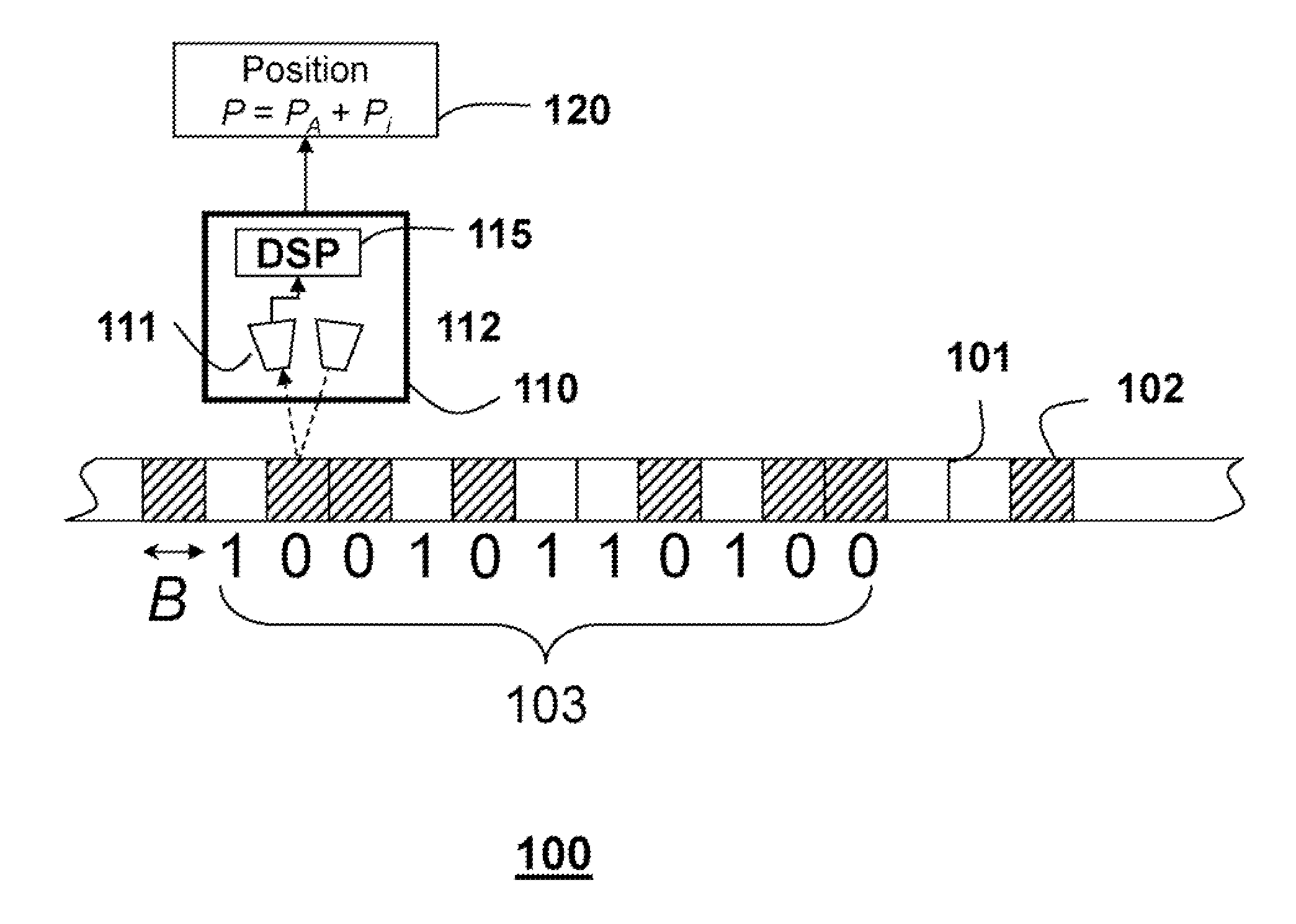
[0024]The embodiments of our invention provide a method for determining high precision position estimates for absolute single track linear encoders.

[0025]Absolute Scale

[0026]FIG. 1 shows a scale 100 of an absolute encoder for one embodiment of our invention. Details of the scale are described in the related U.S. application Ser. No. 13 / 100,092, incorporated herein by reference. The scale is used to determine a high-resolution position P=PA+Pi 120.

[0027]The scale can include alternate light reflecting 101, and non-reflecting 102 marks. Each mark is B microns wide, which the scale resolution.

[0028]The width B of each mark is a half-pitch. In one embodiment, B is 20 microns. A readhead 110 is mounted at some distance and parallel to the scale. The readhead includes a sensor 111, a (LED) light source 112, and an optional lens. The sensor can be a detector array of N sensors, e.g., N is 2048. The array can be complementary metal-oxide-semiconductor (CMOS) or charge coupled device (CCD). ...


PUM


Abstract

A position is determined by sensing a signal corresponding to a subsequence of marks in a non-periodic sequence of the marks on a scale. A coarse position PA is determined by matching the subsequence with all possible subsequences of the non-periodic sequence. Zero-crossings corresponding to rising edges of the signal and zero-crossings corresponding to falling edges of the signal are detected. An incremental position Pi is determined using the zero-crossings. The coarse and the incremental position are summed to obtain the position.

Description

RELATED APPLICATION [0001]This application is related to U.S. application Ser. No. 13 / 100,092, “System and Method for Measuring Positions,” filed by Veeraraghavan et al. on May 3, 2011, and incorporated herein by reference.FIELD OF THE INVENTION [0002]The invention generally relates to position measurement devices, and in particular to measuring positions with absolute encoders.BACKGROUND OF THE INVENTION[0003]Position estimation is an important task in industrial automation, and similar applications. Devices, such as numerically controlled (CNC) machines, drill bits, robot arms or laser cutters, and assembly lines need position measurements. Feedback control is often used for precision position measurements. It is desired to determine positions at high sampling rates to enable accurate feedback control.[0004]Optical encoders are typically used to measure incremental or relative positions. A scale having regularly spaced marks is used along with a readhead including sensors to estim...

Claims


Application Information

Patent Timeline
Patent Type & Authority Applications(United States)
IPC IPC(8): G06F15/00
CPCG01D5/34792G01D5/2455G01D5/34746G01D5/34794
Inventor AGRAWAL, AMITTHORNTON, JAY
Owner MITSUBISHI ELECTRIC RES LAB INC
Why Eureka
Try Eureka