
Dual Injector System For Diesel Emissions Control

a dual-injector system and diesel engine technology, applied in the direction of engines, machines/engines, mechanical equipment, etc., can solve the problems of increasing production, inventory and service costs, peter-hoblyn patent does not provide for the injection of two different reagents, and valentine application does not disclose how. to achieve the effect of reducing oxides of nitrogen (nox) emissions

Active Publication Date: 2008-04-17
TENNECO AUTOMOTIVE OPERATING CO INC
View PDF14 Cites 32 Cited by
  • Summary
  • Abstract
  • Description
  • Claims
  • Application Information

AI Technical Summary

Benefits of technology

[0010]The present invention provides methods and apparatus for injecting fluid, such as an aqueous urea solution or hydrocarbons such as diesel fuel, into an exhaust stream in order to reduce oxides of nitrogen (NOx) emissions from diesel engine exhaust. More particularly, the present invention provides a dual-injector system for diesel emissions control and corresponding methods.

Problems solved by technology

Further, the varying engine sizes from less than 2 liters in passenger cars up to 16 liters in heavy duty trucks each requires different amounts of metered reagent to be injected into the exhaust leading to a wide array of differing injector sizes and designs for each different application, thereby increasing production, inventory and service costs.
However, the system disclosed in the Peter-Hoblyn patent does not provide for the injection of two different reagents and, in fact, only injects gaseous ammonia formed from the hydrolysis of aqueous urea in an upstream process.
However, the disclosed system only injects one reducing agent into the exhaust stream, and only in one location at any given time.
Furthermore, the Valentine application does not disclose how the wide range of reagents needed for engine operating conditions could be met given the single injector in front of each catalyst.
The temperature limitations of each catalyst would prevent simultaneous injection using both injectors for high flow rates.

Method used


Image

  • Dual Injector System For Diesel Emissions Control
  • Dual Injector System For Diesel Emissions Control
  • Dual Injector System For Diesel Emissions Control

Examples


Embodiment Construction

[0022]The ensuing detailed description provides exemplary embodiments only, and is not intended to limit the scope, applicability, or configuration of the invention. Rather, the ensuing detailed description of the exemplary embodiments will provide those skilled in the art with an enabling description for implementing an embodiment of the invention. It should be understood that various changes may be made in the function and arrangement of elements without departing from the spirit and scope of the invention as set forth in the appended claims.

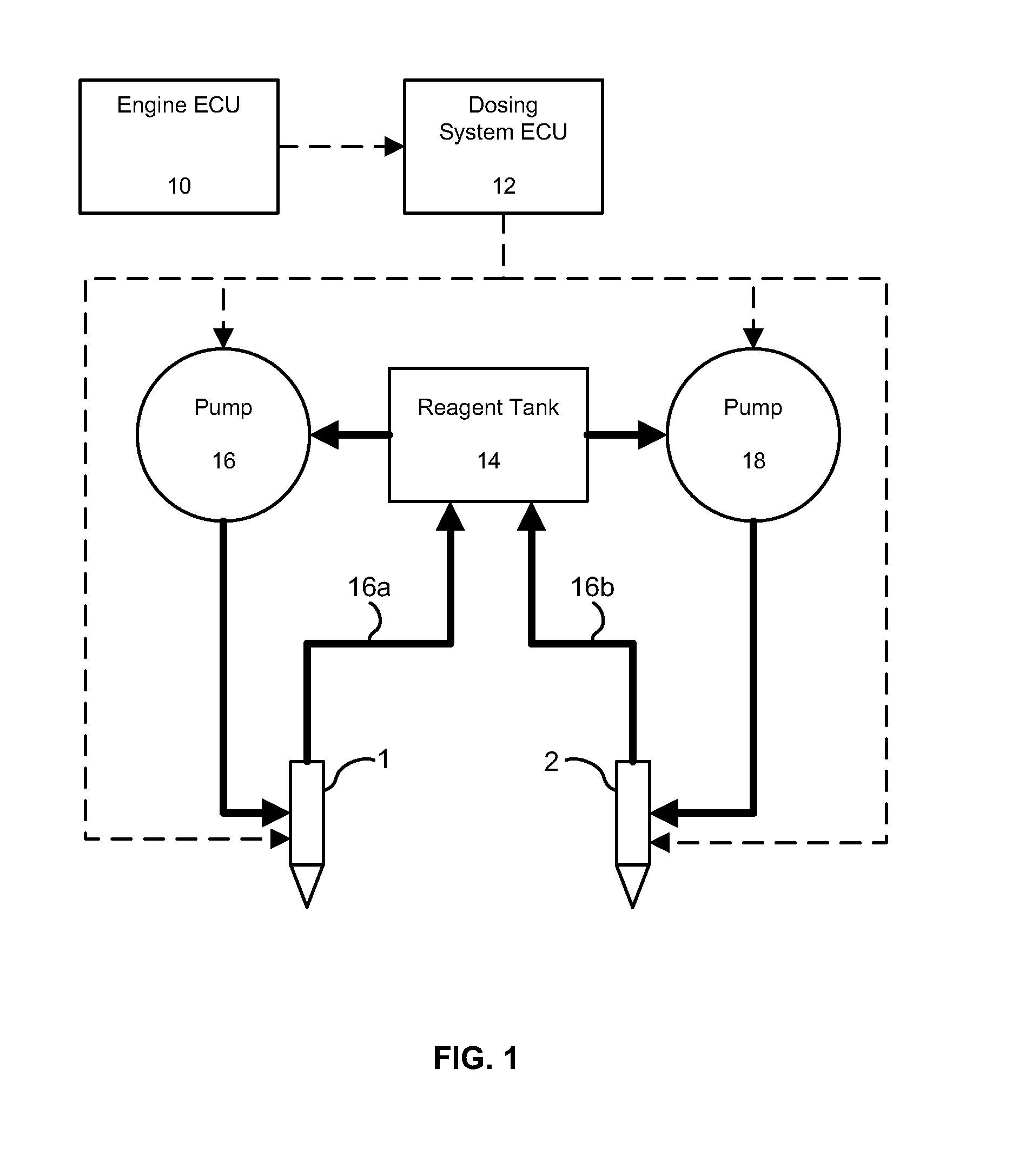
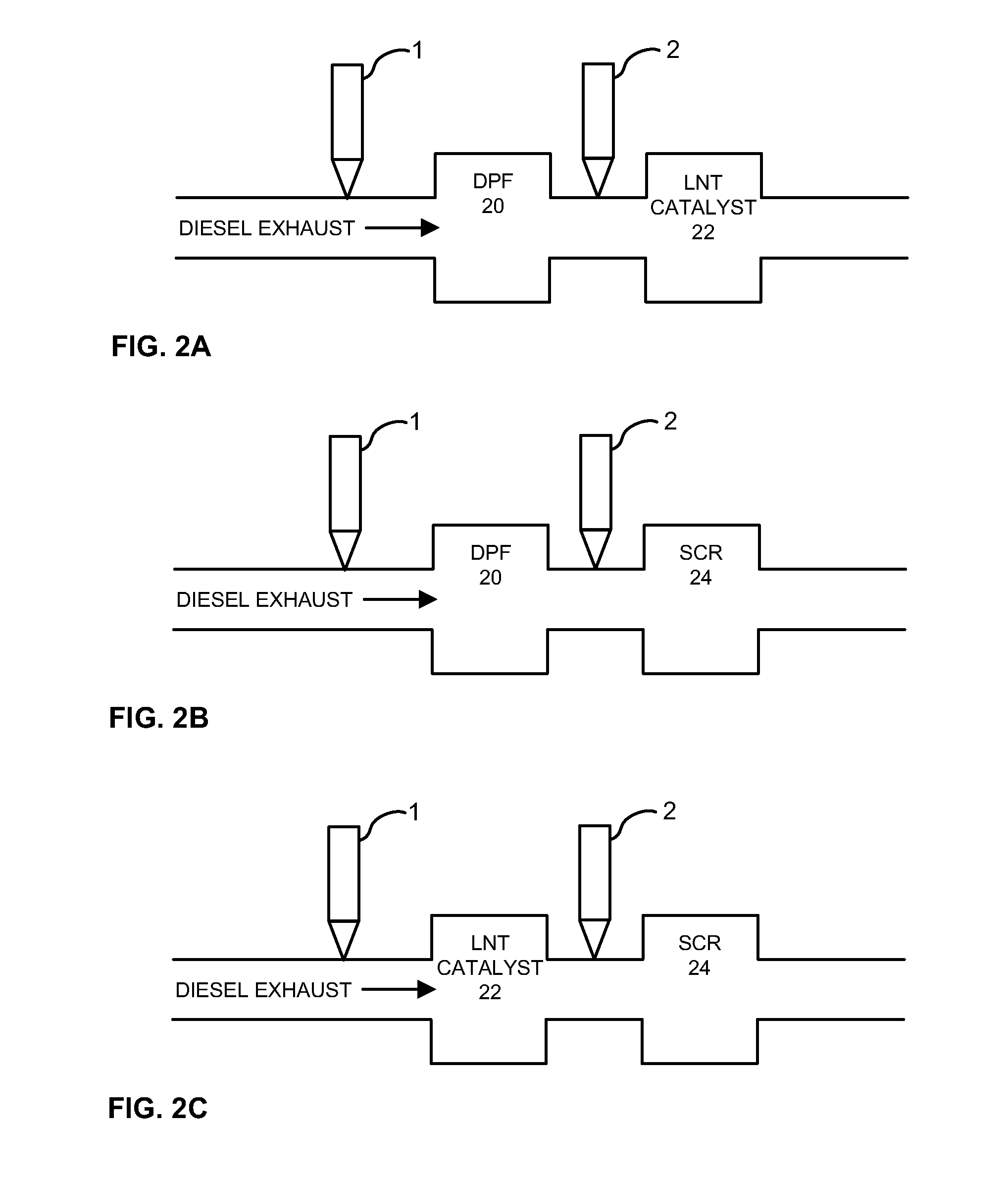
[0023]FIG. 1 shows a block diagram of an example embodiment of the present invention. The dosing system ECU 12 contains a software program capable of driving two 12V DC positive displacement pumps 16, 18, each of which feeds respective injectors 1, 2 containing similar or different sized orifice plates which may be operated at similar or different pressures, frequencies and percentage on-time. The ECU 10 may supply engine operating parameters ...


PUM


Abstract

The present invention provides methods and apparatus for injecting fluid, such as an aqueous urea solution, into an exhaust stream in order to reduce oxides of nitrogen (NOx) emissions from diesel engine exhaust. More particularly, the present invention provides a dual-injector system for diesel emissions control and corresponding methods.

Description

CROSS-REFERENCE TO RELATED APPLICATIONS[0001]This application claims the benefit of, under 35 U.S.C. 119(e), U.S. Provisional Patent Application No. 60 / 851,104, filed Oct. 11, 2006, which application is hereby incorporated by reference herein.FIELD OF THE INVENTION[0002]The present invention relates generally to the reduction of emissions produced by diesel engines. In particular, the present invention provides methods and apparatus for injecting fluid, such as an aqueous urea solution or hydrocarbons such as diesel fuel, into an exhaust stream in order to reduce oxides of nitrogen (NOx) emissions from diesel engine exhaust. More particularly, the present invention provides a dual-injector system for diesel emissions control and corresponding methods.BACKGROUND OF THE INVENTION[0003]The control of diesel engine emissions through aftertreatment systems typically involves the use of technology such as a diesel particulate filter for control of particulates and a lean-NOx trap (LNT) or...

Claims


Application Information

Patent Timeline
Patent Type & Authority Applications(United States)
IPC IPC(8): F01N3/10
CPCF01N3/0253F01N3/0814F01N3/0821F01N3/0871F01N3/208F01N2610/02Y02T10/24F01N2610/14F01N2610/146F01N2610/1473F01N2900/08F01N2900/1814F01N2610/03Y02T10/12F01N3/00F01N3/36
Inventor REBA, PETER JOSEPHBACCARI, GREGORY JOHNELDREDGE, THOMAS V.VALENTINE, JAMES M.
Owner TENNECO AUTOMOTIVE OPERATING CO INC
Learn More