Apparatus and method for radiation imaging

a radiation imaging and apparatus technology, applied in the field of radiation imaging, to achieve the effect of easy entry into the proper register

Inactive Publication Date: 2008-04-17
FUJIFILM CORP
View PDF4 Cites 27 Cited by
  • Summary
  • Abstract
  • Description
  • Claims
  • Application Information

AI Technical Summary

Benefits of technology

[0041]It should be noted that the phrase “displayed in superposition” means displaying the shape information in such a way that it can be recognized simultaneously with an object and it is not necessarily required that the shape information be displayed in agreement with the shape of the object.
[0042]According to the present invention having the features described above, breasts may be radiographed with the right breast imaged first, then the left breast, in such a way that shape information is acquired when imaging the right breast and at the time when the left breast is being imaged, the shape information for the right breast is presented on a display together with the left breast being imaged, or alternatively, the shape information for the right breast is displayed on an imaging table on which the breast is placed or a press plate that is compressing the breast. Thus, by viewing the shape of the already imaged right breast as it is in a superposed relationship with the left breast to be imaged next, the radiologist can take a radiation image of the left breast while assuring that the positions of the two breasts are easily brought into proper register.
[0043]Hence, according to the present invention, radiation images of the two objects in pair can be obtained with their positions being brought into register in a consistent and advantageous manner, as in mammography which involves viewing of the right and left breasts placed side by side.

Problems solved by technology

However, in each of those technologies, the radiation images taken of the right and left breasts are processed and their positions are brought into register on the mammograms; this is by no means an approach that ensures that the positions of the right and left breasts and the like can be properly adjusted during imaging.

Method used


Image

  • Apparatus and method for radiation imaging
  • Apparatus and method for radiation imaging
  • Apparatus and method for radiation imaging

Examples


Embodiment Construction

[0052]On the pages that follow, the radiation imaging apparatus and method of the present invention are described in detail with reference to the preferred embodiments shown in the accompanying drawings.

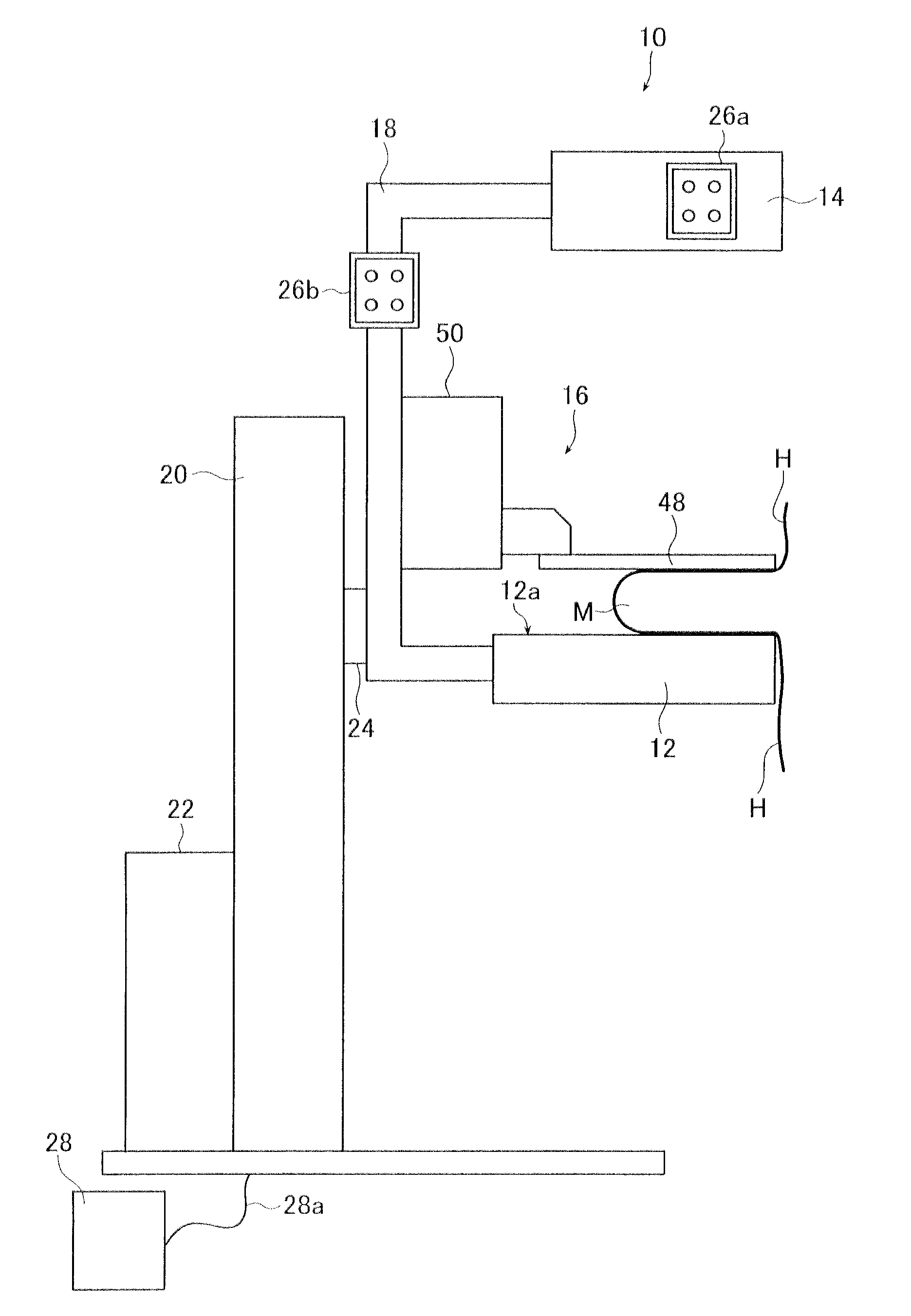
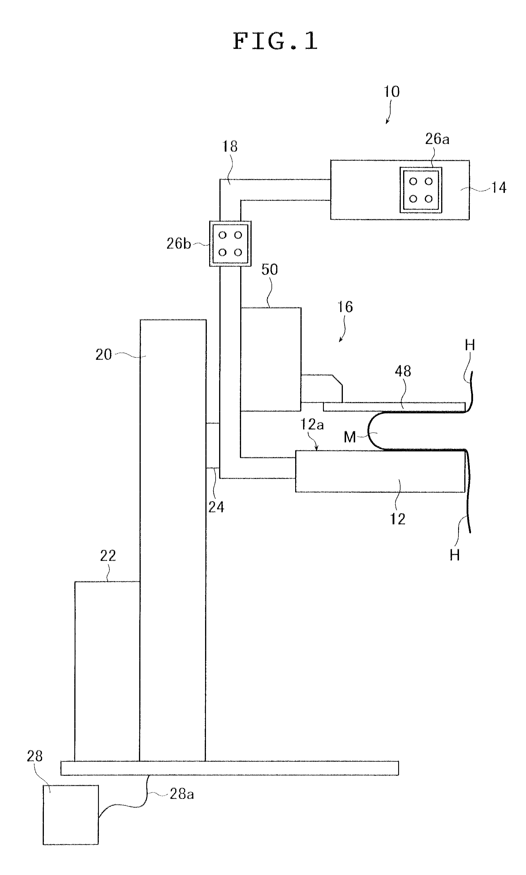
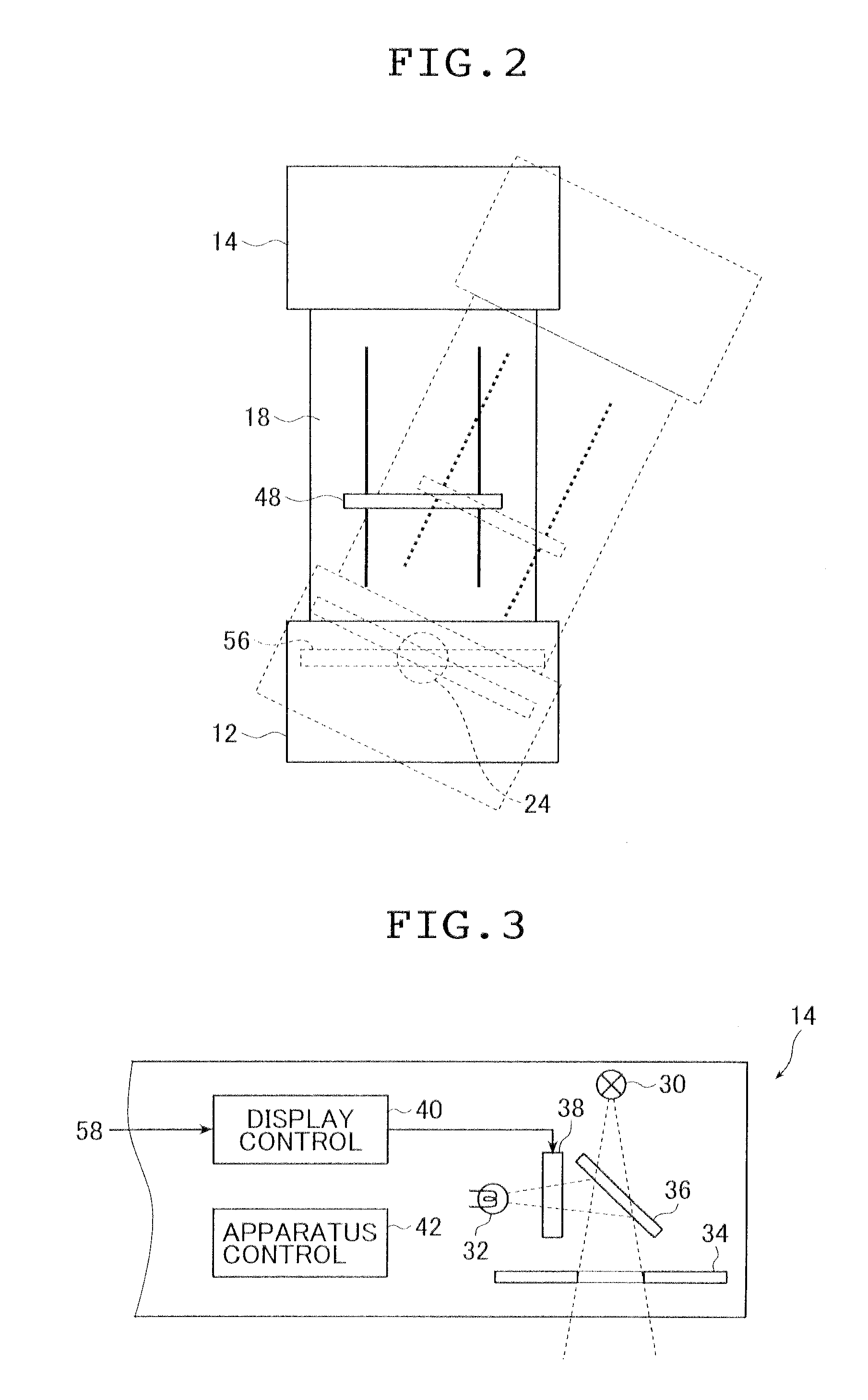
[0053]FIG. 1 shows in concept an embodiment of the radiation imaging apparatus of the present invention for implementing the radiation imaging method of the present invention, as it is applied as a breast's radiation image taking apparatus.

[0054]As FIG. 1 shows, the breast's radiation image taking apparatus which is generally indicated at 10 (and hereinafter referred to as the mammographic unit 10) is basically composed of an imaging table 12, an irradiating section 14, a compressing means 16, an arm 18, a base 20, and an X-ray irradiating high-voltage power supply 22. The illustrated breast mammographic unit 10 is basically the same as the ordinary breast's radiation image taking apparatus, except that it has the shape information acquiring means and display means that will be descr...


PUM


Abstract

The radiation imaging apparatus includes a radiation source for irradiating an object, a radiation image detector having a radiation-receiving plane that receives radiation from the radiation source through the object, for detecting a radiation image of the object, a shape information acquiring device for acquiring shape information that represents a shape of the object and a shape information display device that displays the shape information such that it reproduces a position of the object as occurs when the shape information is acquired. The radiation imaging method takes a first radiation image of a first object and generates shape information which represents the shape of the first object, inverts the shape information and displays inverted shape information such that it reproduces a position of the first object and takes a second radiation image of a second object.

Description

[0001]The entire contents of documents cited in this specification are incorporated herein by reference.BACKGROUND OF THE INVENTION[0002]The present invention relates to the technical field of radiation imaging (radiation image taking / recording), in particular, to an apparatus and a method for radiation imaging by which the right and left breasts of a subject can be taken with proper register attained between their positions in mammography.[0003]In breast cancer screening, the success rate of early detection that is achieved through physical examination by inspection and palpation only is improved if it is combined with mammography by a radiation image taking apparatus solely intended for breasts (which is hereinafter referred to as a breast imaging apparatus); hence, breast cancer screening that is currently practiced involves the use of a breast imaging apparatus in addition to (or in place of) inspection and palpation.[0004]The breast imaging apparatus comprises an imaging table ...

Claims


Application Information

Patent Timeline
Patent Type & Authority Applications(United States)
IPC IPC(8): G01T1/166
CPCA61B5/103A61B6/4291A61B6/0414A61B5/1077A61B6/502
Inventor KASHIWAGI, NOBUHIKO
Owner FUJIFILM CORP
Why Eureka
Try Eureka