Eureka AIR delivers breakthrough ideas for toughest innovation challenges, trusted by R&D personnel around the world.

Audio Signal Processing System

a processing system and audio signal technology, applied in the field of audio signal processing system, can solve the problems of inability to decide in advance the characteristics, etc. of the masking sound, and the contents of the sound cannot be re-expressed in the surrounding area,

Inactive Publication Date: 2008-04-17
YAMAHA CORP
View PDF7 Cites 14 Cited by
  • Summary
  • Abstract
  • Description
  • Claims
  • Application Information

AI Technical Summary

Benefits of technology

[0018] According to the present invention, it is feasible to suppress such a circumstance that, in emitting different sound contents in neighboring areas, the contents leak out to surrounding areas to have a mutual influence on each other.

Problems solved by technology

In such case, such a problem comes up that, when the speaker is provided on an each area basis, respective sound contents leak out to the surrounding areas.
However, in the hall, the tearoom, and the like, since the sound contents are reproduced in answer to a user's desire every area, it is impossible to decide in advance the characteristics, etc. of the masking sound.

Method used


Image

  • Audio Signal Processing System
  • Audio Signal Processing System
  • Audio Signal Processing System

Examples


first embodiment

A: First Embodiment

(A-1: Configuration of First Embodiment)

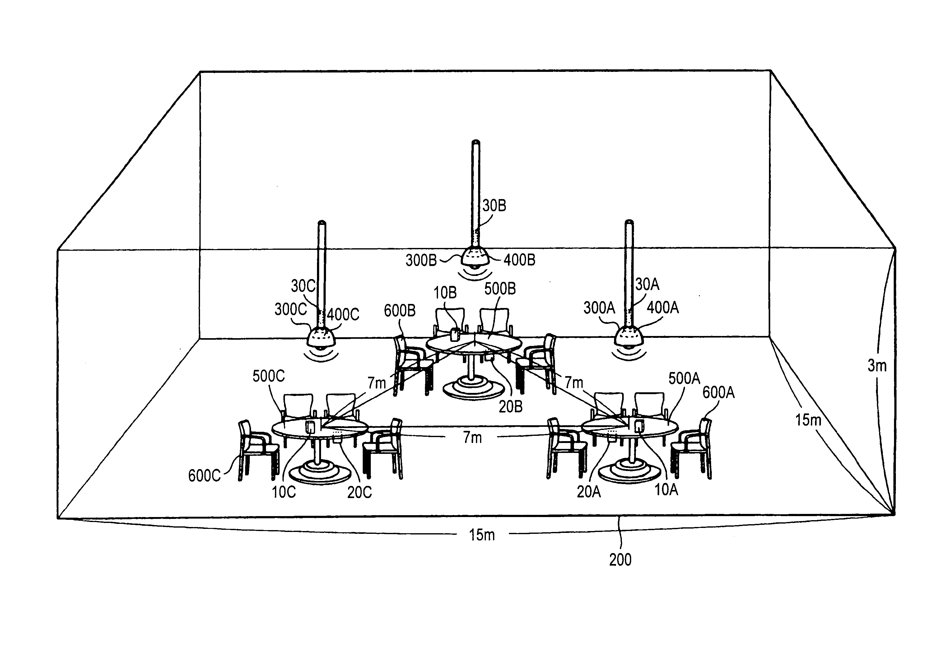
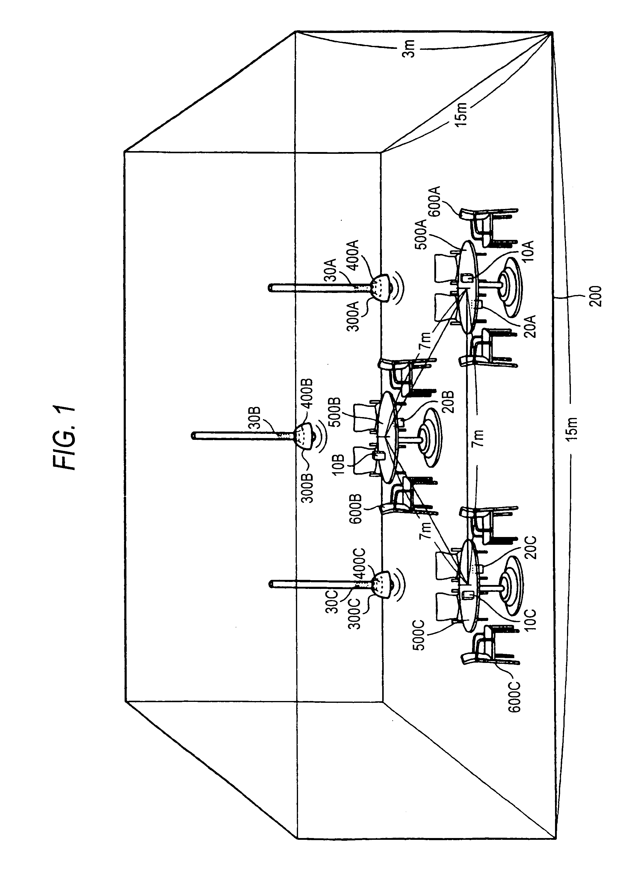
[0037]FIG. 1 is a view showing an outline of a hall 200 into which an audio signal processing system 1 according to the present invention is installed. As shown in FIG. 1, the hall 200 with sides of 15 meter and a ceiling height of 3 meter is prepared. Three tables 500A, 500B, and 500C are provided in the hall 200 to be separated mutually such that distances between their centers are set to 7 meter respectively. Four chairs 600A, 600B, and 600C are arranged around each table respectively. Also, illuminations 300A, 300B, 300C are hung from the ceiling over the tables 500A, 500B, and 500C respectively. A lamp of the illumination is surrounded by a “lampshade”.

[0038] In the present embodiment, explanation is made of the case where the hall 200 with sides of 15 meter and a ceiling height of 3 meter is prepared. It is needless to say that a scale of the hall is not limited to such values. Also, in the present embodiment, expla...

second embodiment

(B-2: Operation of Second Embodiment)

[0112] An operation of the audio signal processing system 1 according to the present invention will be explained hereunder. In the present operational example, like the first embodiment, the audio signal processing system 1 executes the acoustic processes of respective contents in compliance with a flowchart shown in FIG. 8. In the present operational example, since the process contents in steps SA 300 to SA500 in the flowchart are different from those in the operational example in the first embodiment, steps SA 300 to SA500 will be explained mainly hereunder.

[0113] Also, the acoustic process applied to the contents A by the audio signal processing device 30A will be explained hereunder. But the acoustic processes applied to the contents B and C are carried out similarly by the units B and C.

[0114] Graphs given in FIGS. 12A to 12C show the sound volume levels of the contents A, B, and C respectively. An ordinate denotes the sound volume level o...


PUM


Abstract

An audio signal processing system includes: a receiving section which receives a plurality of audio signals, a process period specifying section which specifies a silent period in other audio signals except a particular audio signal that are received by the receiving section, respectively, a sound volume level adjusting section which decreases a sound volume level of the particular audio signal, in a period specified by the process period specifying section as a silent period in any of the other audio signals, and an outputting section which outputs the particular audio signal whose sound volume level is adjusted by the sound volume level adjusting section.

Description

BACKGROUND OF THE INVENTION [0001] The present invention relates to the technology to process an audio signal. [0002] In a hall, a tearoom, and the like, for example, the necessity of providing different sound contents (information, music, etc.) every nearby area arises occasionally. In such case, such a problem comes up that, when the speaker is provided on an each area basis, respective sound contents leak out to the surrounding areas. In the prior art, various measures such as an adjustment in an arrangement of the speakers or a sound volume level of the contents, a provision of a sound insulating wall at a boundary between the areas, and the like have been taken against the above problem. [0003] For example, in Patent Literature 1, the technology called the sound image normalizing system to form a directional acoustic space by a parametric speaker is disclosed. Also, in Patent Literature 2, the technology called the active noise control to reduce a noise by generating the sound ...

Claims


Application Information

Patent Timeline
Patent Type & Authority Applications(United States)
IPC IPC(8): H03G3/20H04R29/00
CPCH03G3/32G10K11/175H04R29/00H04K3/825H04K2203/12H04K3/42H04K3/43H04K3/45G10K11/1752
Inventor TAKEUCHI, EIJI
Owner YAMAHA CORP
Why Eureka
Eureka Blog
Learn More