Linear guide device

a guide device and linear technology, applied in the direction of bearings, bearings, shafts and bearings, etc., can solve problems such as sealing damage, and achieve the effect of not resulting in sealing damag

Inactive Publication Date: 2008-04-17
ROBERT BOSCH GMBH
View PDF5 Cites 12 Cited by
  • Summary
  • Abstract
  • Description
  • Claims
  • Application Information

AI Technical Summary

Benefits of technology

[0007]The object of the present invention, therefore, is to provide a linear guide device

Problems solved by technology

When a guide carriage is slid onto the guide rail equipped with the cover strip,

Method used


Image

  • Linear guide device
  • Linear guide device
  • Linear guide device

Examples


Embodiment Construction

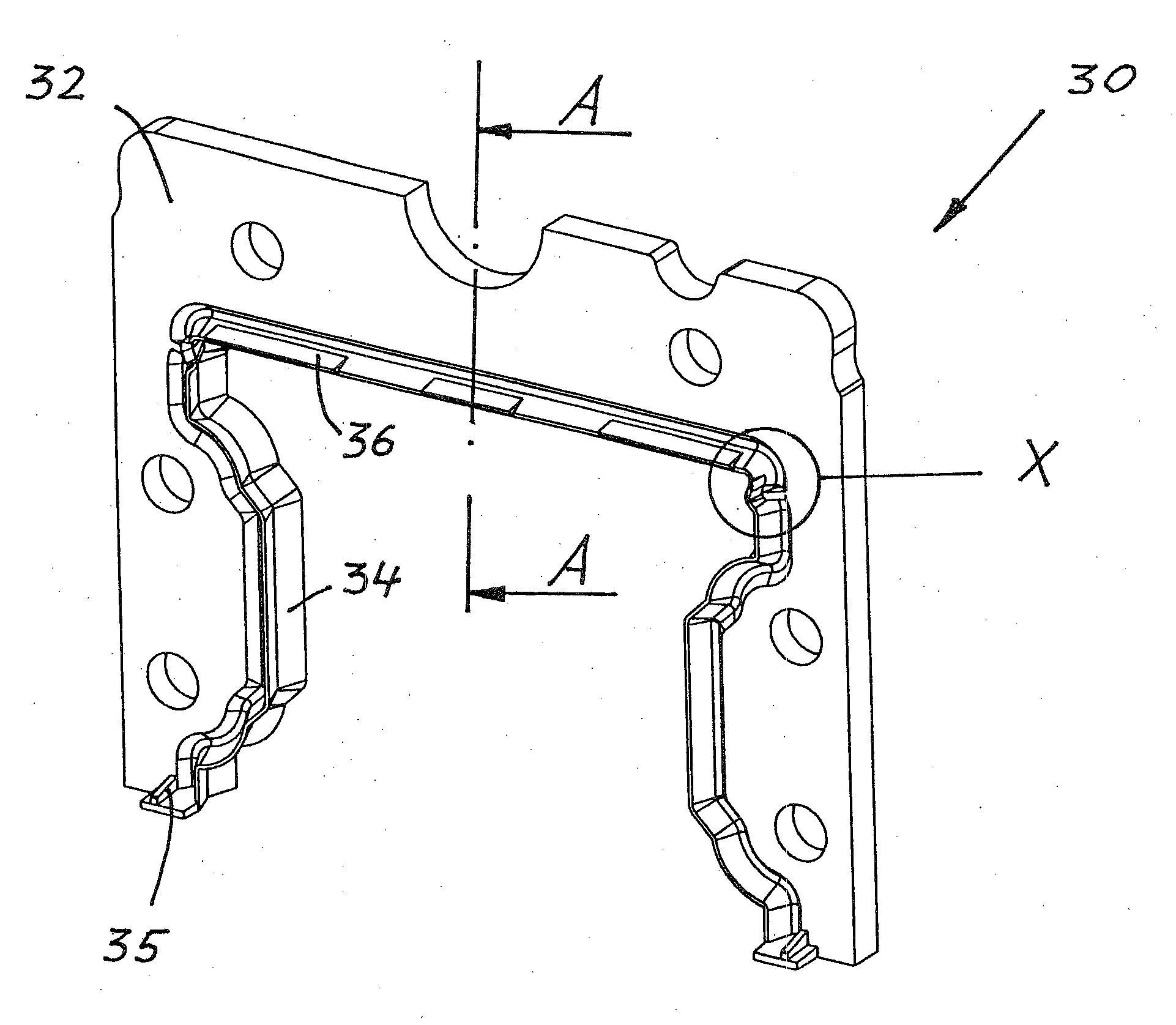
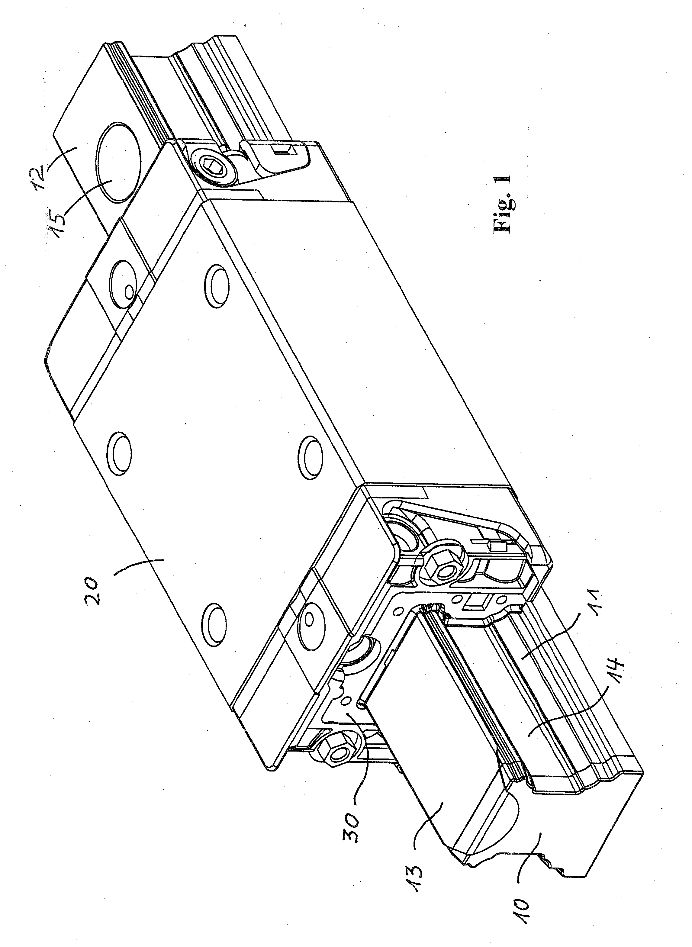
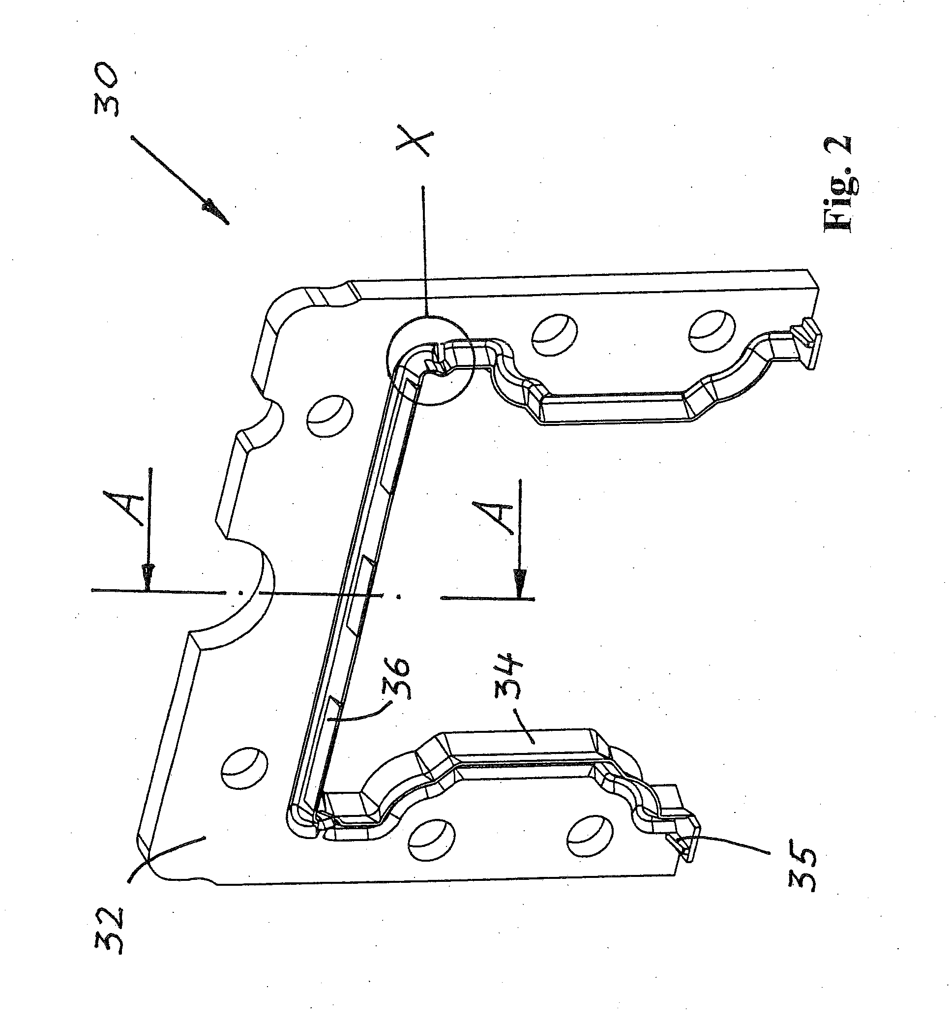
[0017]The linear guide device shown in FIG. 1 is a rail guide with a guide base 10 designed as a profiled guide rail. Guide base 10 has two lateral surfaces 14, a top surface 12, and a bottom surface, via which it is mounted on a higher-order assembly. To this end, through-bores 15 are provided in guide base 10, which extend from top surface 12 to the bottom surface and are penetrated by not-shown fastening means. Through-bores 15 are closed via a cover strip 13, which covers essentially the entire top surface and a portion of lateral surfaces 14. A smooth surface is obtained as a result, which is free of gaps and edges.

[0018]Guide base 10 is equipped with tracks 11 on its lateral surfaces for not-shown balls, via which a rotor 20—designed as a guide carriage—is supported on guide base 10 along the longitudinal axis. Rotor 20 wraps around guide base 10 in a nearly U-shaped manner and includes tracks, which are diametrically opposed to tracks 11, by way of which a carrier channel is ...


PUM


Abstract

A linear guide device includes a guide base with two lateral surfaces and a top surface covered with a cover strip, a rotor that wraps around at least a portion of the guide base, so that the rotor is supported on the guide base as it moves longitudinally along its longitudinal axis, and at least one scraper unit installed on the rotor on its end faces extending orthogonally to the longitudinal axis, wherein the scraper unit includes a main body and at least one sealing lip, which is at least partially in contact with the top surface and the lateral surfaces of the guide base. The sealing lip of the scraper unit is equipped, at least partially, with at least one reinforcing element.

Description

CROSS-REFERENCE TO A RELATED APPLICATION[0001]The invention described and claimed hereinbelow is also described in German Patent Application DE 10 2006 048 282.4 filed on Oct. 12, 2006. This German Patent Application, whose subject matter is incorporated here by reference, provides the basis for a claim of priority of invention under 35 U.S.C. 119(a)-(d).BACKGROUND OF THE INVENTION[0002]The present invention generally relates to linear guide devices.[0003]More particularly, present invention is based on a linear guide device that includes a guide base with two lateral surfaces and a top surface covered with a cover band, a rotor that wraps around at least a portion of the guide base, so that the rotor is supported on the guide base as it moves longitudinally along its longitudinal axis.[0004]At least one scraper unit is installed on the rotor on its end faces extending orthogonally to the longitudinal axis. The scraper unit includes a main body and at least one sealing lip, which is...

Claims


Application Information

Patent Timeline
IPC IPC(8): F16C33/72F16C29/08
CPCF16C29/086F16C29/0645
Inventor HAUB, ALFRED
Owner ROBERT BOSCH GMBH
Why Eureka
Try Eureka