Hot-water supply apparatus

a technology of hot water supply and hot water, which is applied in the direction of heating types, domestic cooling devices, defrosting, etc., can solve the problems of water-heat exchanger freezing, and achieve the effect of reducing the time required for defrosting

Active Publication Date: 2008-04-24
TOSHIBA CARRIER CORP
View PDF7 Cites 22 Cited by
  • Summary
  • Abstract
  • Description
  • Claims
  • Application Information

AI Technical Summary

Benefits of technology

[0010] The method of using the heat of hot water of a hot-water tank to eliminate frost while performing a reverse cycle defrosting is advantageous in reducing the time required to defrost, as described above, but disadvantageous in that a water-heat exchanger is frozen when low-temperature water flows in a water-heat exchanger.

Problems solved by technology

The method of using the heat of hot water of a hot-water tank to eliminate frost while performing a reverse cycle defrosting is advantageous in reducing the time required to defrost, as described above, but disadvantageous in that a water-heat exchanger is frozen when low-temperature water flows in a water-heat exchanger.

Method used


Image

  • Hot-water supply apparatus
  • Hot-water supply apparatus
  • Hot-water supply apparatus

Examples


Embodiment Construction

[0021] Hereinafter, an embodiment of the invention will be explained with reference to the accompanying drawings.

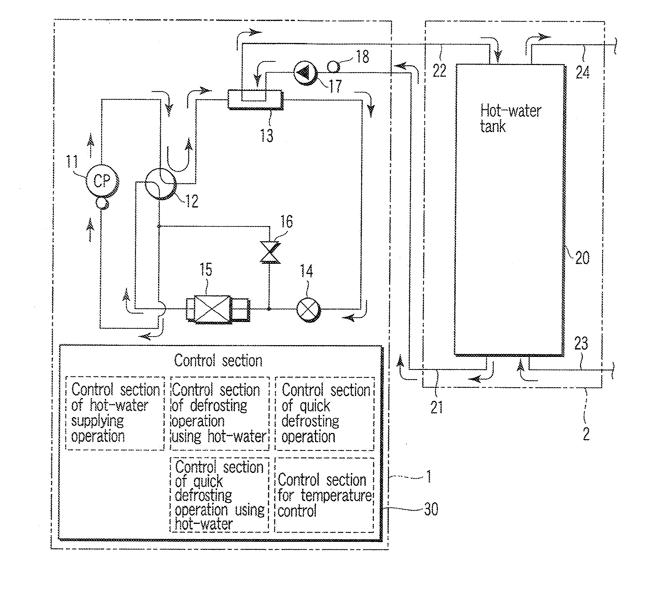
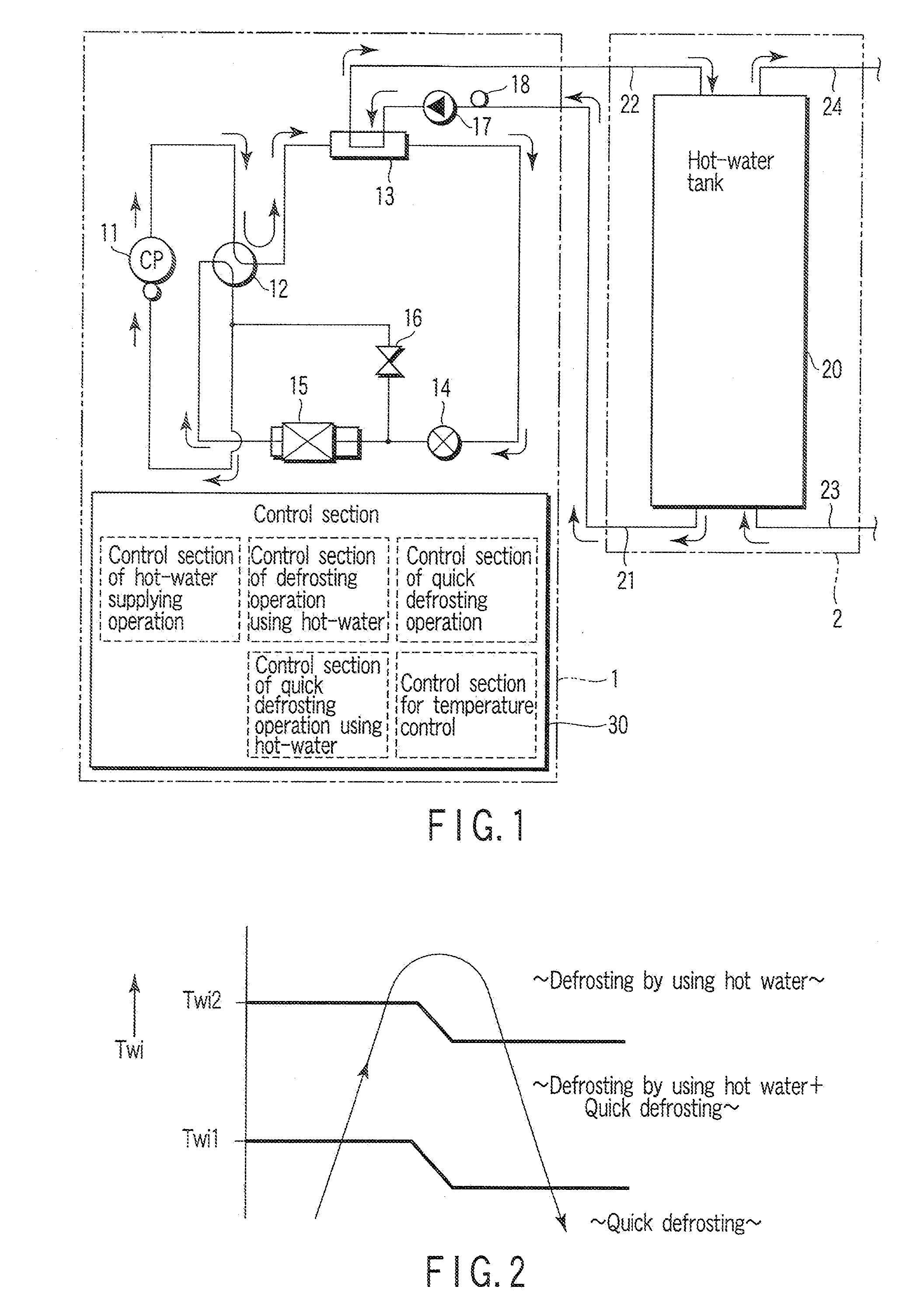
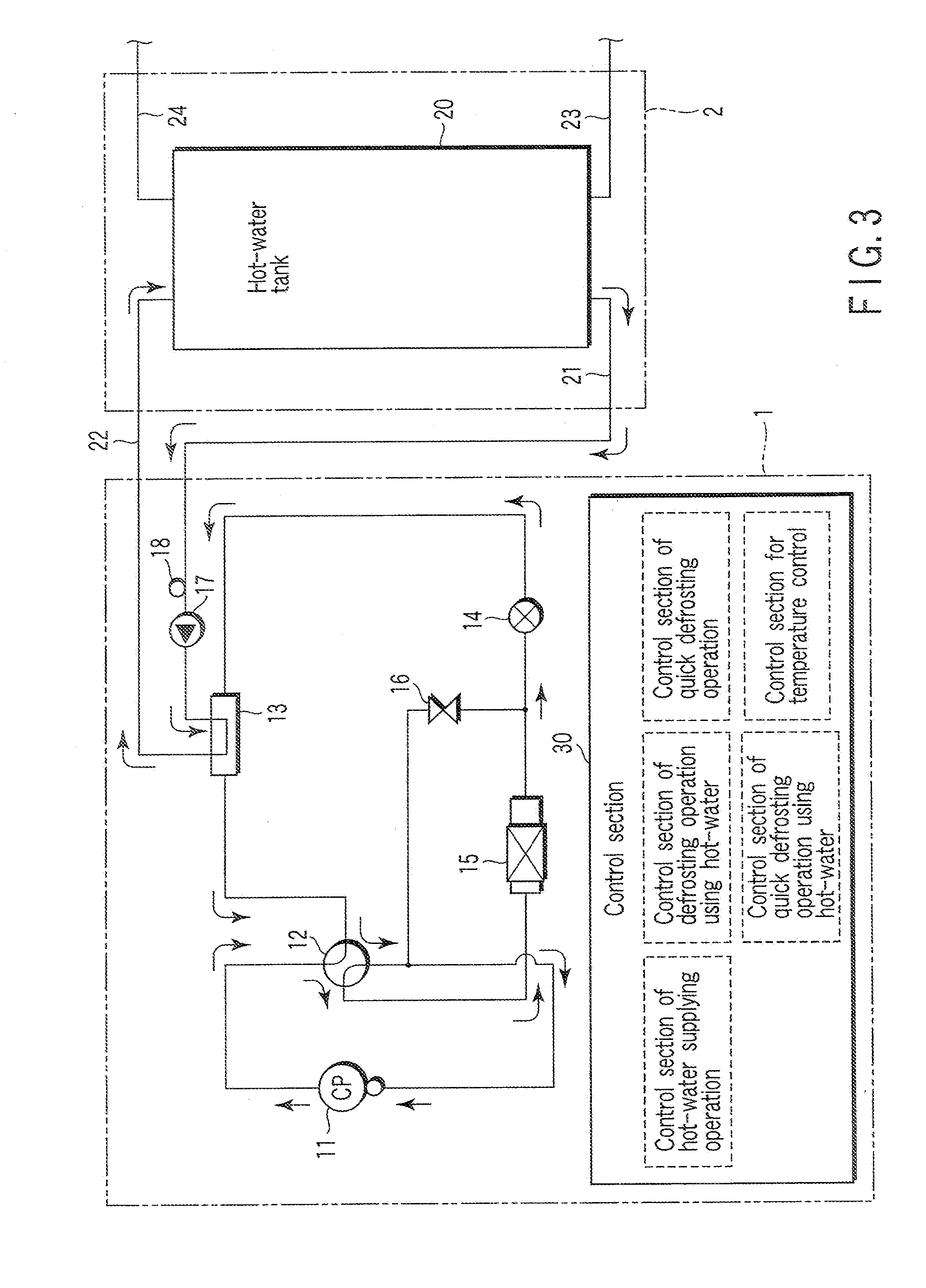
[0022] As shown in FIG. 1, a hot-water supply apparatus comprises a heat source unit 1 and a hot-water tank unit 2.

[0023] The heat source unit 1 has a heat pump refrigeration cycle formed by sequentially piping and connecting a compressor 11, a four-way valve 12, a water-heat exchanger 13, a flow rate control valve 14 and an outdoor heat exchanger 15. In the piping between the flow rate control valve 14 and outdoor heat exchanger 15 to the piping of the suction side of the compressor 11, a bypass 19 is connected through a two-way valve 16. An externally guided circulation piping (water side) 21 is connected to the inlet side of the water-heat exchanger 13 through a pump 17, and a circulation piping (hot-water side) 22 is connected to the outlet side of the water-heat exchanger 13. The circulation piping (hot-water side) 22 is guided to the outside. The circulation pipin...


PUM


Abstract

Defrosting operation is possible by causing refrigerant discharged from a compressor to flow to an outdoor heat exchanger, and returning the refrigerant passed through the outdoor heat exchanger to the compressor through a water-heat exchanger, while operating a pump. Quick defrosting operation is possible by causing refrigerant discharged from a compressor to flow to an outdoor heat exchanger, and returning the refrigerant passed through the outdoor heat exchanger directly to the compressor, while stopping a pump. The temperature of water that has flowed into a water-heat exchanger is detected. According to the detected temperature, the defrosting operation using hot water and quick defrosting operation are selectively executed.

Description

CROSS REFERENCE TO RELATED APPLICATIONS [0001] This is a Continuation Application of PCT Application No. PCT / JP2006 / 300253, filed Jan. 12, 2006, which was published under PCT Article 21(2) in Japanese. [0002] This application is based upon and claims the benefit of priority from prior Japanese Patent Application No. 2005-092742, filed Mar. 28, 2005, the entire contents of which are incorporated herein by reference.BACKGROUND OF THE INVENTION [0003] 1. Field of the Invention [0004] The present invention relates to a hot-water supply apparatus, which stores hot water in a hot-water tank by circulating water of a hot-water tank through a water-heat exchanger of a heat pump refrigeration cycle. [0005] 2. Description of the Related Art [0006] There is a hot-water supply apparatus, which has a heat pump refrigeration cycle having a compressor, a water-heat exchanger and an outdoor heat exchanger, and stores hot water in a hot-water tank by circulating water of a hot-water tank through a w...

Claims


Application Information

Patent Timeline
Patent Type & Authority Applications(United States)
IPC IPC(8): F25D21/12
CPCF24D17/02F25B2339/047F25B47/025
Inventor OOKOSHI, SEIJITANABE, TOMOAKISATO, MASAAKIHORI, MASATOYAMAZAKI, YOSHITERU
Owner TOSHIBA CARRIER CORP
Why Eureka
Try Eureka